
Flashing Led Controller
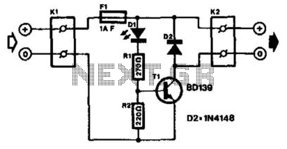
The described circuit utilizes an LED with an integrated flasher, which serves as a visual indicator while simultaneously controlling a load through a transistor switch. The LED is connected in series with the base-emitter junction of a bipolar junction transistor (BJT), specifically the BD139. This configuration allows the LED to modulate the transistor's operation, effectively switching the connected load on and off at a defined flash rate.
The load, which can either be a relay or a lamp, is connected to terminal K2. The operation of the load is directly influenced by the switching action of the transistor, which is driven by the LED's flashing. It is crucial to ensure that the collector current of the BD139 does not exceed its maximum rating of 750 mA. Should the application require a higher current capacity, a power Darlington transistor can be used as an alternative. Darlington transistors are known for their high current gain, allowing them to switch larger loads while maintaining a compact design.
Under no-load conditions, the circuit draws a current of 20 mA, which is relatively low, making it suitable for battery-operated devices or applications where power efficiency is essential. Proper consideration of the load's power requirements and the transistor's specifications will ensure reliable operation and longevity of the circuit. The LED with integrated flasher is connected in series with the base-emitter junction of transistor Tl. Thus, the l oad connected to K2 is switched on and off in rhythm with the flash rate. This load can be a relay or a lamp. The maximum collector current of the transistor (of the BD139 = 750 mA) must not be exceeded. If that is not sufficient, a power Darlington can be used, which will give some amperes. The current drawn by the circuit under no-load conditions amounts to 20 mA. 🔗 External reference
Related Circuits
Discrete blinking LEDs are convenient, but the blink rate and duration are not configurable. Experimentation with transistors, resistors, and capacitors was attempted to modify the blinking LED behavior. Ultimately, the abundance of additional electronic components led to the conclusion...
This RF Wave Absorption meter detects signals from 10 centimeters to 10 meters, depending on the setting of the 22 MegOhm gain adjustment potentiometer and the transmitter power. The RF signal is captured through germanium OA91 diodes and rectified...
This LED thermometer is designed for in home use, to read temperatures between about 60 and 78 degrees Fahrenheit. It is based around a precision temperature sensor IC, the LM34DZ. This sensor require no calibration and can measure temperatures...

Voltage regulator ICs (78xx series) provide a steady output voltage, in contrast to a widely fluctuating input supply, when the common terminal is grounded. The 78xx series of voltage regulator integrated circuits (ICs) are widely utilized in electronic circuits to...
This circuit is an automatic street light controller. The sensor used to detect changes in light is an LDR (Light Dependent Resistor). The working principle of the LDR is that when exposed to light, its resistance value decreases, while...

Average vending machines are commonly found at railway stations, airports, fast-food restaurants, and even within companies. When a switch is pressed, the machine dispenses a cup of the selected beverage. Although this process appears straightforward, it involves complex logic,...