
Flashing LED unit

This LED flasher circuit utilizes two CMOS NE555 timers to create a visually appealing rotating LED effect. The first NE555 timer (IC1) is configured as an astable multivibrator, generating a square wave output at a frequency of 4Hz. This output is responsible for driving the first set of LEDs (D1 to D6), which are arranged in a manner that enhances the rotating effect. The duty cycle of 50% ensures that the LEDs are turned on and off equally, contributing to a balanced illumination pattern.
The second NE555 timer (IC2) serves as a trigger pulse inverter, which modifies the output signal from IC1 to control the second set of LEDs (D7 to D12). This configuration allows for a more complex flashing pattern, further enhancing the visual effect. The use of the CMOS variant of the NE555 is advantageous due to its low power consumption, making it suitable for operation with small power sources, such as 3V button cells.
The design choice to use sinking mode for the NE555 timers at low voltages is critical for optimal performance. In this mode, the timers pull the current through the LEDs to ground rather than supplying it, which can lead to improved reliability and brightness at lower voltages. This is particularly important in battery-operated applications where efficiency is paramount.
Finally, LED D13 is incorporated into the circuit as a constant indicator, remaining permanently lit to provide a visual reference of the circuit’s operational state. This design not only serves aesthetic purposes but also enhances user awareness of the circuit's functionality. Overall, the circuit exemplifies effective use of simple components to create engaging visual effects while maintaining low power requirements.The circuit given here is designed as an LED flasher which produces a rotating effect when the LEDs are arranged properly. The circuit has very low current consumption and can be operated from even 3V button cells. The IC 1 (CMOS NE555) is wired as an astable multivibrator wired at a duty cycle of 50% and 4Hz frequency and drives LEDs D1 to D6.
The second IC, IC2 (CMOS NE555) is working as a trigger pulse inverter and drives LEDs D7 to D12. The circuit is arranged such that the ICs sink the current consumed by the LEDs. At low operating voltages like 3V, the CMOS NE 555 performs better when arranged in sinking mode rather than in sourcing mode. The LED D13 remains permanently ON. 🔗 External reference
Related Circuits
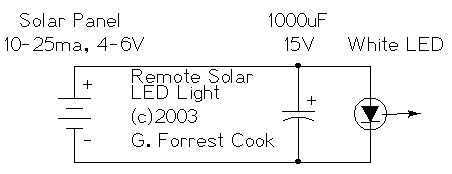
The remote solar powered LED light takes advantage of the current limited nature of solar photovoltaic cells. If light shines on the solar array, current will flow through the circuit. For a typical size of solar cell, there is...
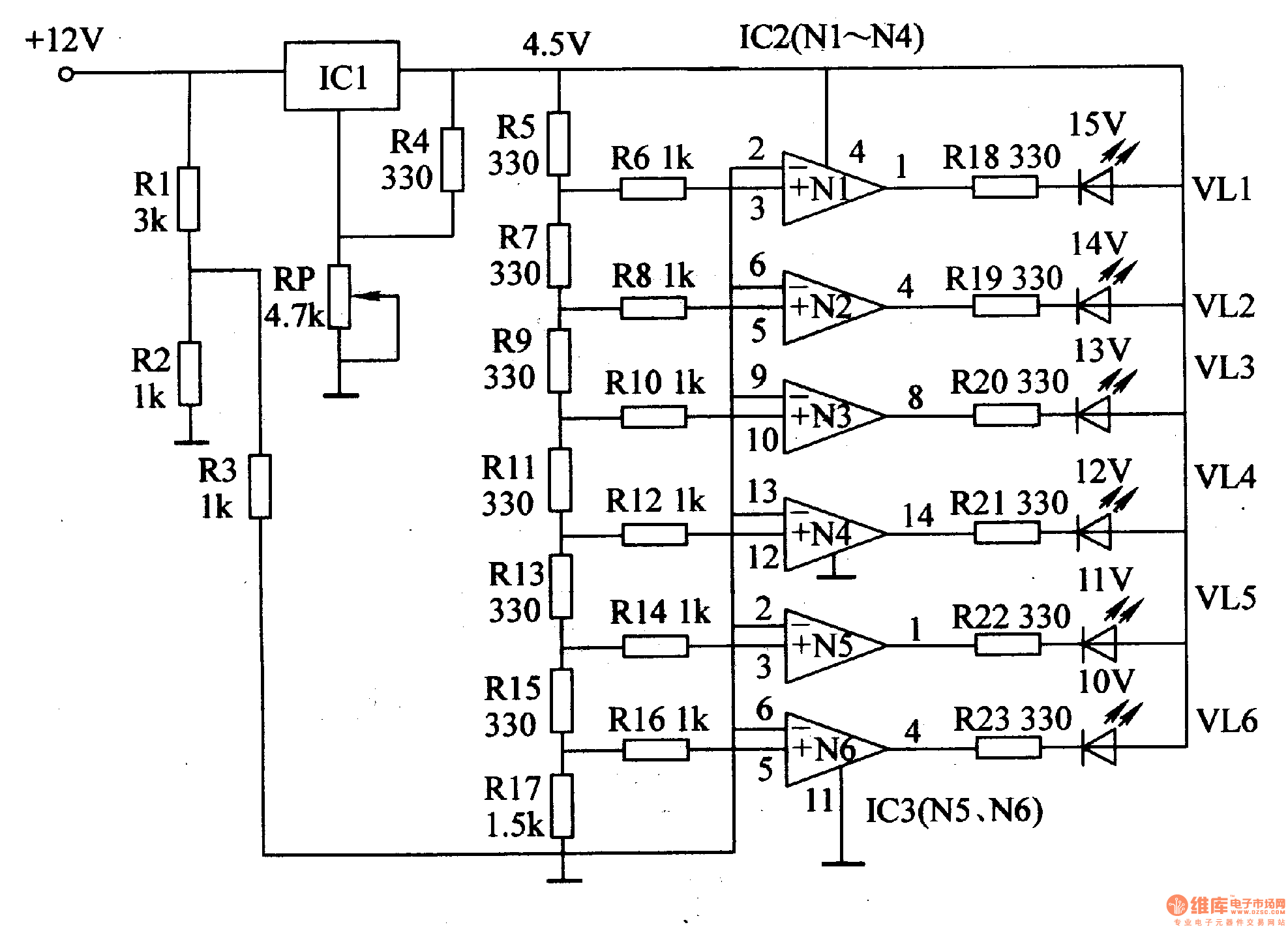
This document introduces an LED car voltmeter constructed using the op-amp LM312 and LED components. It is designed to display six voltage levels ranging from 10V to 15V, with each level representing a 1V increment. The working principle of...
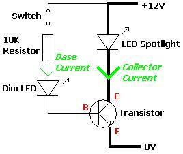
A transistor is an electronic component that allows a small current to control a significantly larger current. This characteristic is valuable in various renewable energy projects and other applications. A basic circuit diagram is provided, featuring a 12V LED...
Discrete blinking LEDs are convenient, but the blink rate and duration are not configurable. Experimentation with transistors, resistors, and capacitors was attempted to modify the blinking LED behavior. Ultimately, the abundance of additional electronic components led to the conclusion...
A battery-status indicator circuit is useful for monitoring portable test equipment and similar devices. LED D1 flashes to attract the user's attention, signaling that the circuit is operational, preventing it from being left on unintentionally. The circuit produces approximately...
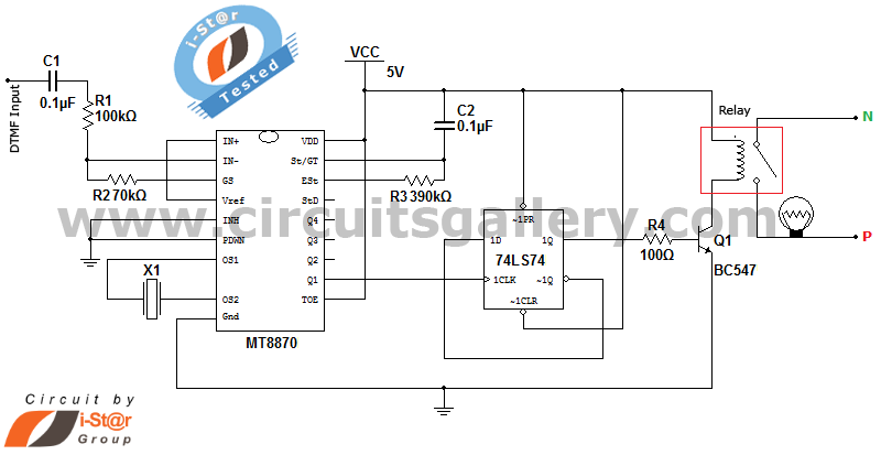
It is possible to control home and office electrical appliances using a mobile phone. This document presents a simple home automation electronic mini project circuit diagram designed for engineering students, allowing the control of electrical appliances without the use...