
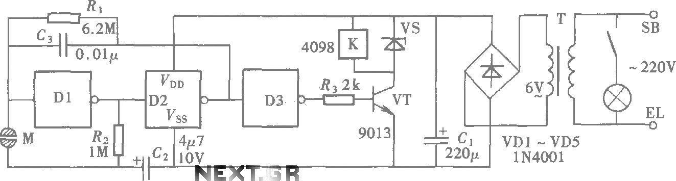
Flashing Mains Lamps circuit

When building and the installation must be ensured that the entire circuit carries power. It is therefore recommended to the circuit board to build a real and not an experimental PCB. R1 = 220 kOhm R2 = 1 M ½ R3 = 10 M? R4, R5, R6 = 10 kOhm P1 = 100 kOhm C1, C2 = 47 uF D1-D4 = 1N4007 D5 = 5.6 V zener T1, T2 = TIC 106d IC1 = CMOS IC 4011 L1, L2 = 220 V, 250 W max lamp
The circuit design described is intended for a flashlight system capable of controlling two 220 V alternating current (AC) lamps. The primary component is a CMOS integrated circuit (IC), specifically the 4011, which is utilized for generating the flashing signal necessary to control the lamps. The circuit employs two thyristors, T1 and T2 (model TIC 106D), to manage the on/off states of the lamps L1 and L2, each rated for a maximum of 250 W at 220 V.
The configuration of the circuit includes several resistors (R1 through R6) and capacitors (C1 and C2) that work together to shape the timing and behavior of the flashing signal. Resistor R1, with a value of 220 kOhm, is likely used to limit current within the circuit, while R2, at 1 MΩ, serves a similar protective role. R3, specified as 10 MΩ, may be part of a timing network that influences the flash rate. Resistors R4, R5, and R6, each at 10 kOhm, are likely used for biasing and stability within the circuit.
The capacitors C1 and C2, both rated at 47 µF, are crucial for the timing characteristics of the flashing mechanism, storing energy to create the desired delay between flashes. Diodes D1 to D4 (1N4007) are used for rectification and protection against reverse polarity, while D5, a 5.6 V zener diode, is employed to regulate voltage within the circuit, ensuring that the IC and other components operate within their specified limits.
Installation of this circuit requires careful attention to ensure that it is built on a robust printed circuit board (PCB) rather than a prototype board, to guarantee safety and reliability when handling high voltages. Proper insulation and spacing between high-voltage components must be maintained to prevent electrical arcing or short circuits. Overall, this design provides a reliable method for controlling high-voltage lamps using a low-power control signal from the CMOS IC, suitable for applications requiring flashing light signals.This is a design for a flashlight that two 220 V alternating lights can control. The flashlight uses only one IC. IC1a IC1c to be used for the flashing signal generation. The output of IC1c thyristor T1 is controlled, it lights up then release L1. IC1c After the signal is again inverted so as L1 L2 lights not lit. When building and the installation must be ensured that the entire circuit carries power. It is therefore recommended to the circuit board to build a real and not an experimental PCB. R1 = 220 kOhm R2 = 1 M ½ R3 = 10 M? R4, R5, R6 = 10 kOhm P1 = 100 kOhm C1, C2 = 47 uF D1-D4 = 1N4007 D5 = 5.6 V zener T1, T2 = TIC 106d IC1 = CMOS IC 4011 L1, L2 = 220 V, 250 W max lamp 🔗 External reference
Related Circuits
A CMOS gate exhibits high input impedance, which allows it to respond to changes in input levels due to human contact, thereby triggering the toggling of gates. The circuit utilizes this characteristic to create a touch lamp switch. The...

This is one of the most accurate and simplest LC inductance/capacitance meters available, which can be easily constructed by an individual. This LC meter is capable of measuring very small inductances ranging from 10 nH to 1000 nH, 1...
Connect the serial cable to the serial port. If using a USB to TTL, RS232, or serial converter, plug it into the USB port. Next, short the Tx pin to the Rx pin or the TxD pin to the...
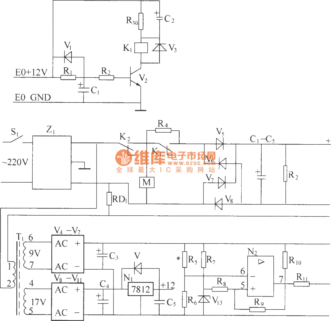
220V (5Hz) alternating voltage passes through the Z1 circuit filter, which filters the signal before sending it to the connection point of the AC over-voltage and under-voltage protection relay K2. During normal operation, the K2 connection point should be...
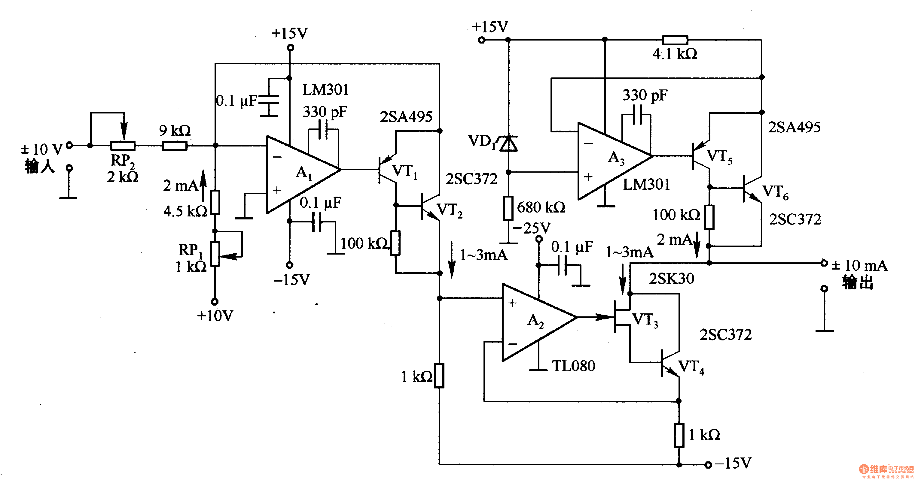
This circuit is designed for voltage-to-current conversion, specifically transforming a ±10V input voltage into a ±1mA output current. The conversion process is facilitated by operational amplifier A1 and transistors VT1 and VT2, which are responsible for altering the current...
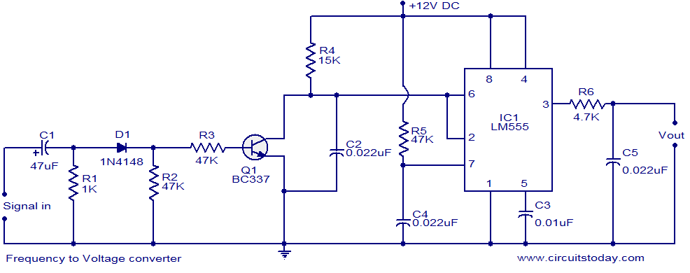
A simple frequency to voltage (F to V) converter circuit utilizing the LM555 Timer IC. This circuit has numerous applications in digital frequency meters, tachometers, and other related devices. The frequency to voltage (F to V) converter is a crucial...