Reuse Old Mobile Phone Battery for LED lighting
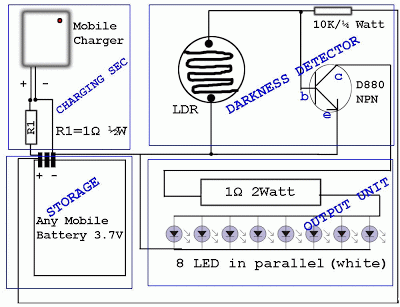
Mobile batteries typically have a lifespan of 2 to 5 years under normal usage, after which they need to be replaced. Currently, inexpensive replacement batteries are available for about $1, but these low-cost options only last 6 to 12 months. A practical solution for used batteries that cannot be reused in mobile devices is to repurpose them in circuits that require lower current. One effective application is using these batteries for LED lighting, resulting in an automatic emergency light powered by discarded mobile batteries.
Repurposing used mobile batteries for LED lighting circuits offers an efficient way to extend the life of these batteries while providing a useful application. The circuit can be designed to operate at lower current levels, ensuring that the remaining charge in the used batteries can effectively power LED lights.
To create an automatic emergency light circuit using these batteries, the following components are recommended:
1. **LEDs**: Select high-efficiency LEDs that require minimal current. The number of LEDs used will depend on the desired brightness and the voltage of the battery.
2. **Battery Holder**: A suitable holder for the mobile battery should be included to ensure secure placement and easy replacement when necessary.
3. **Resistor**: A current-limiting resistor may be required to prevent excess current from flowing through the LEDs, which could lead to overheating and damage. The resistor value can be calculated using Ohm's Law, based on the forward voltage and current rating of the LEDs.
4. **Switch**: A toggle or push-button switch can be incorporated to turn the circuit on and off as needed.
5. **Light Sensor (optional)**: For an automatic feature, a light-dependent resistor (LDR) or a phototransistor can be added to the circuit. This component will allow the LEDs to turn on automatically in low light conditions, making the device suitable for use as an emergency light.
6. **Diode (optional)**: A diode may be included to prevent reverse polarity connection, thereby protecting the circuit from damage if the battery is installed incorrectly.
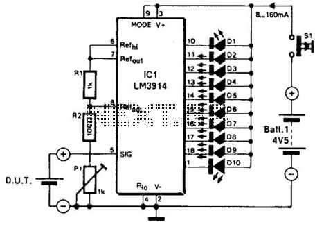
The circuit can be assembled on a printed circuit board (PCB) or a breadboard for prototyping. Proper connections should be made, ensuring that the positive terminal of the battery connects to the anode of the LED and the resistor, while the cathode connects back to the negative terminal of the battery.
This design not only provides a functional application for used batteries but also promotes sustainability by reducing electronic waste. The resulting automatic emergency light can serve as a reliable source of illumination during power outages or emergencies, effectively utilizing resources that would otherwise be discarded.Normally mobile batteries have a lifespan of 2-5 years under normal usage. But then we have to replace them. Nowadays there are cheap replacement batteries which cost no more than 1$. But these low cost batteries run only 6-12 months. What to do with the used batteries, which can`t be reused in mobiles Well, easy solution is to use the batteries i n a circuit that requires less current. We can use them for LED lighting. Normally mobile batteries have a lifespan of 2-5 years under normal usage. But then we have to replace them. Nowadays there are cheap replacement batteries which cost no more than 1$. But these low cost batteries run only 6-12 months. What to do with the used batteries, which can`t be reused in mobiles Well, easy solution is to use the batteries in a circuit that requires less current. We can use them for LED lighting. Thus your automatic lighting emergency light is ready which runs by your waste Mobile Battery. 🔗 External reference
Warning: include(partials/cookie-banner.php): Failed to open stream: Permission denied in /var/www/html/nextgr/view-circuit.php on line 713
Warning: include(): Failed opening 'partials/cookie-banner.php' for inclusion (include_path='.:/usr/share/php') in /var/www/html/nextgr/view-circuit.php on line 713
