
float charger for nimh cells
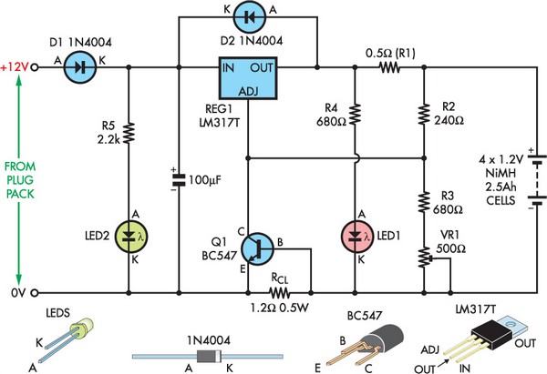
The LM317 voltage regulator circuit is designed to provide a stable output voltage for charging NiMH batteries. The configuration includes essential components such as resistors, diodes, LEDs, and a transistor, each serving a specific purpose to enhance the performance and safety of the charging process. The resistors R2 and R3, along with the adjustable trimpot VR1, allow for precise control of the output voltage, crucial for maintaining the health of the NiMH cells during charging.
The circuit's protection features are particularly noteworthy. The inclusion of diode D1 prevents damage from reverse polarity, ensuring that the circuit remains functional even if the power supply is connected incorrectly. This is an important safety feature that minimizes the risk of component failure. Additionally, the combination of resistor RCL and transistor Q1 acts as a current limiter, which is vital during short-circuit conditions or when connecting batteries that are significantly discharged. This feature protects both the circuit and the batteries from excessive current, which could lead to overheating or damage.
LED indicators provide visual feedback on the circuit's status. LED2 indicates the input voltage to the charger, while LED1, in conjunction with a 680-ohm resistor, shows the output status and ensures that the regulator maintains a minimum load. This is particularly important as it prevents the output voltage from rising too high when the battery is nearly fully charged, which could otherwise result in battery damage.
The design is adaptable for various configurations, allowing for the charging of multiple NiMH cells in series. The provided table of alternative values for different battery configurations helps in customizing the circuit for specific applications, ensuring optimal charging performance within the specified current ranges.
For thermal management, the choice of packaging for the LM317 is critical. The TO-220 package requires a heatsink for higher current applications, while the TO-3 package can operate without one under certain conditions. This consideration is essential for maintaining the reliability and longevity of the voltage regulator, especially in designs that involve charging multiple cells simultaneously.
Overall, this LM317-based float charger circuit is an effective solution for maintaining NiMH batteries, providing both performance and safety through its thoughtful design and component selection.Although not a new device, the LM317 is still a high-performance regulator. Its output voltage is essentially immune to fluctuations in load, supply voltage and temperature and this makes it ideal as the central element in a float charger for NiMH cells. Float charging has the advantage of keeping the cells fully charged and ready to use without t he potential damage of long-term trickle charging or the cost of low-discharge cells. This works because NiMH cells do not have the memory problems associated with Ni-cads. The circuit is based on a conventional LM317 regulator. Resistors R2 & R3 and trimpot VR1 set the maximum output voltage to between 1. 3V and 1. 4V per cell. VR1 should be adjusted for a value of 1. 35V per cell at the regulator output. Resistor R2 has been fixed at 240O. The formula for the voltage output is: Vout = 1. 25*(1 + (R3 + VR1)/R2). Diode D1 protects the circuit against reverse polarity of the power supply and protects the LM317 should the power be disconnected while it is still connected to a charged battery pack. Resistor RCL and transistor Q1 limit the maximum current in the event of a short circuit or the connection of a severely discharged battery pack.
LED2 provides an indication of voltage input to the charger. LED1 and the 680O resistor provide the same function for the charger output and also provide a minimum load for the regulator when the battery pack is nearing full charge. This is necessary to keep the regulator output from drifting up and damaging the batteries. The circuit uses an external DC plugpack and is suitable for four NiMH cells rated at 2. 5Ah. Table 1 gives alternative values for 1-10 batteries in series at peak charge currents of between 200mA to 600mA.
If you are using the specified plug-pack and the TO-220 packaged LM317T, you will need a heatsink rated at 12 °C/W or better for any design other than the 200mA single cell charger. A TO-3 packaged device with the correct plug-pack will be OK without a heat-sink for any of the 200mA configurations and up to four cells charging at 400mA.
🔗 External reference
Related Circuits
This is a straightforward circuit designed for charging lead-acid batteries using the PB137 regulator. The PB137 is utilized in the lead-acid battery charger circuit due to its ability to provide... The PB137 voltage regulator is a linear regulator specifically suited...
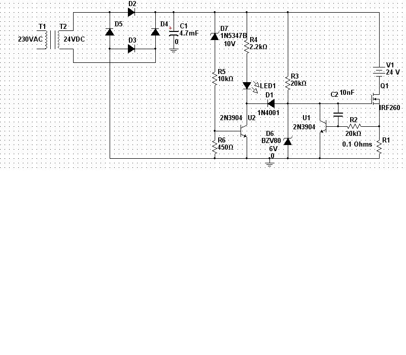
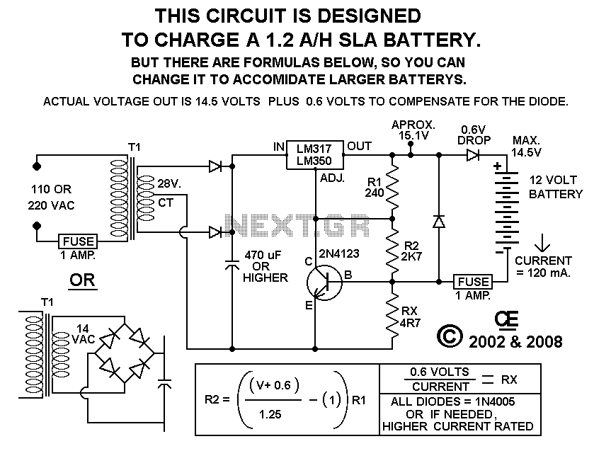
A 240/24Vac (rms) transformer is utilized, which after rectification and filtration provides approximately 30Vdc. It is crucial to select the transformer and diode ratings appropriately to meet the required specifications. In the current limiting stage, transistor U1, Q1, and...
Charger for car battery power supply. Refer to the webpage for an explanation of the power supply-related circuit diagram. The battery charger indicator circuit described above enhances the appearance of a simple battery charger. This circuit serves as a...
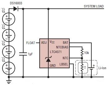
A simple solar-powered battery charger circuit can be designed using the LTC4071 Li-Ion/Polymer Shunt Battery Charger System with Low Battery Disconnect. When VCC reaches the programmed float voltage (4.1V with ADJ floating), the LTC4071 shunts excess current not used...
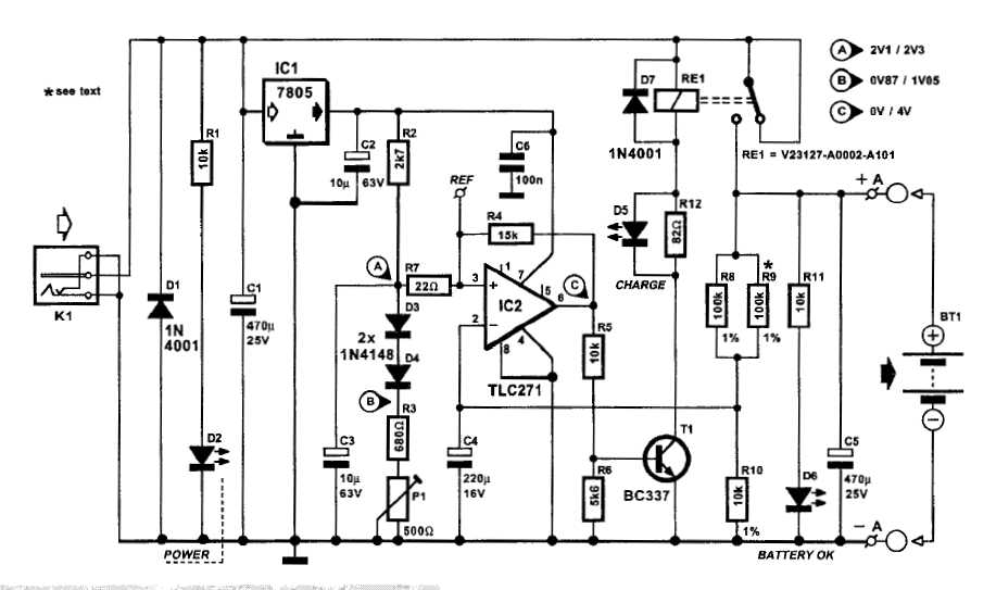
An automatic battery charger initiates the charging process when the battery voltage falls below a specified threshold and ceases charging once the voltage exceeds a predetermined maximum value. The setup is straightforward; simply connect two alligator clips to the...
Using this circuit will give good charging results to the gel cell battery used in the metal detector or any other similar and smaller type battery. This charger is both current and voltage regulated. The output is not short...