
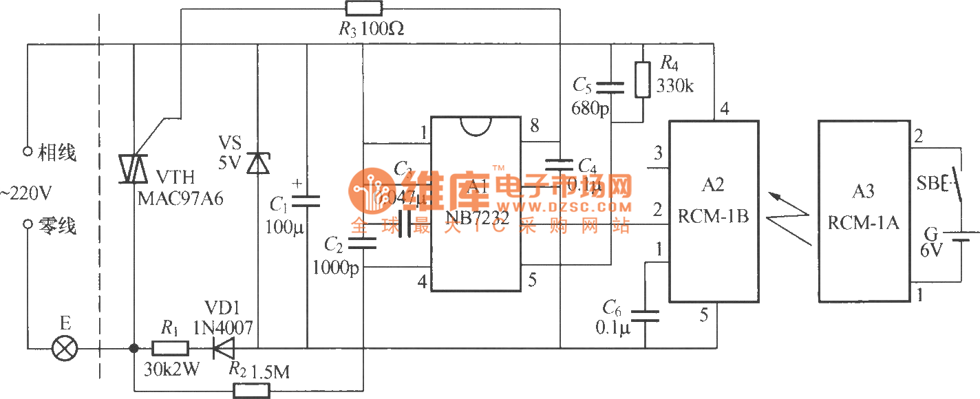
Radio remote control dimmer circuit
The radio remote control dimmer circuit is designed to provide users with the convenience of remote operation while maintaining efficient control over lighting levels. The core components include a micro radio transmit/receive module, which facilitates wireless communication between the remote control and the dimmer. The light modulation ASIC plays a crucial role in adjusting the brightness of the connected lighting fixture based on the signals received from the remote control.
The circuit's simplicity is one of its key advantages, as it requires only two output wires, which significantly reduces installation complexity compared to traditional dimmer circuits that may require additional wiring for control signals. This two-wire system allows for seamless integration into existing lighting setups without the need for extensive modifications.
In terms of functionality, the remote control allows users to adjust the brightness of the lights from a distance, enhancing user convenience and comfort. The reliability of the circuit ensures consistent performance, making it suitable for various applications, including residential, commercial, and industrial lighting systems. The use of a micro radio module also minimizes interference and ensures stable communication, which is essential for effective dimming control.
Overall, the radio remote control dimmer circuit offers an innovative solution for modern lighting control, combining ease of use, reliability, and efficient design.As shown in the diagram above, it is a radio remote control dimmer circuit. The radio remote control dimmer circuit adopts micro radio transmit/receive module and light modulation ASIC. So the circuit is concise and easy to produce. It works reliably. And the whole switch has only two wires for output.It can directly use it to replace the ordinary lighting..
🔗 External reference
Related Circuits
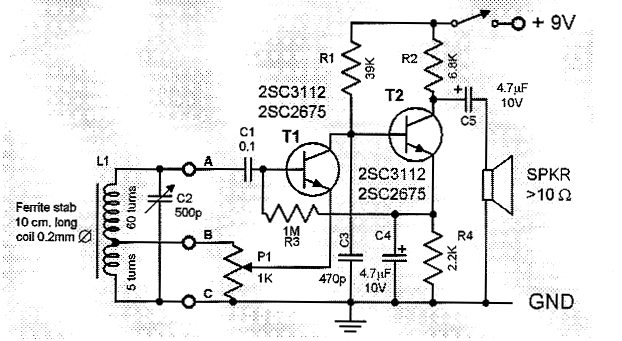
This is a compact and straightforward FM radio receiver capable of tuning into local FM stations. Its minimalistic design renders it suitable for various applications. The FM radio receiver circuit typically consists of several key components that work together to...
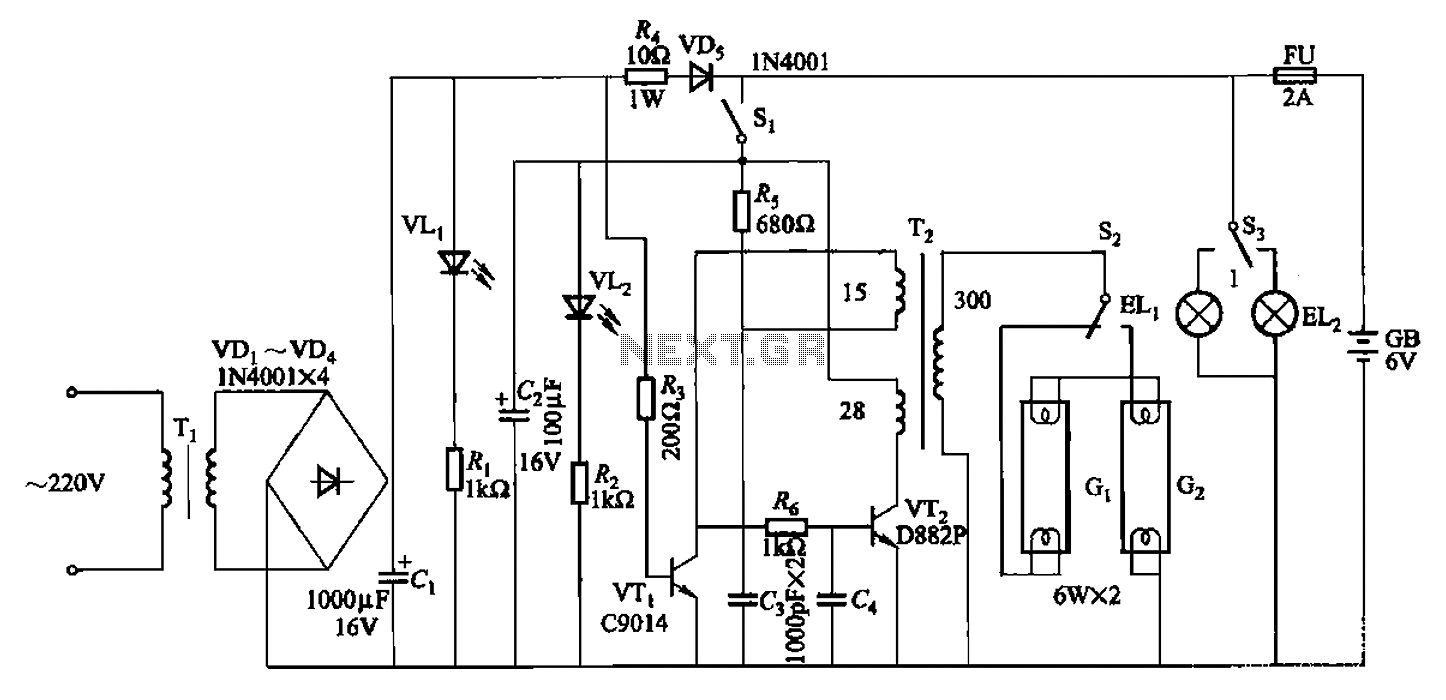
The 786A multi-functional double-tube fluorescent emergency circuit is illustrated in Figure 2-129. This circuit shares similarities with Figure 2-125. The 786A multi-functional double-tube fluorescent emergency circuit is designed to provide illumination during power outages or emergencies. It utilizes two fluorescent...
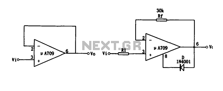
Figure (a) illustrates a voltage follower circuit, which serves as a specific instance of an in-phase amplifying circuit. The input signal originates from an integrated operational amplifier. At the conclusion of the introduction phase, the feedback resistor is set...
The regenerative effect of a 4-quadrant inverter necessitates power dissipation in some form. In large industrial drives, this power is typically re-inverted back onto the national grid. However, for smaller applications, implementing a braking circuit is advisable. For low-power...
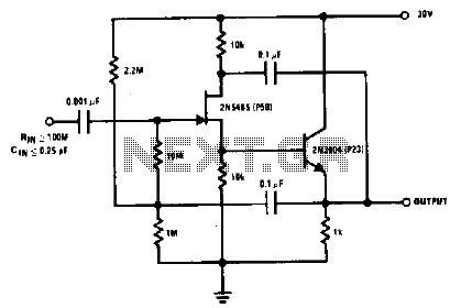
The 2N5485, which has a very low-capacity legacy, is always operated as a source follower with gate bias bootstrap. In this circuit, nothing is left to chance in reducing input capacitance. The 2N5485 is a JFET (Junction Field Effect Transistor)...
This document presents a collection of engaging and challenging electronic circuits that can be built for enjoyment. The author has a long-standing passion for electronics, having studied the subject since middle school and developed numerous circuits over the years....
Warning: include(partials/cookie-banner.php): Failed to open stream: Permission denied in /var/www/html/nextgr/view-circuit.php on line 713
Warning: include(): Failed opening 'partials/cookie-banner.php' for inclusion (include_path='.:/usr/share/php') in /var/www/html/nextgr/view-circuit.php on line 713