
Flyback Transformer Driver Circuit

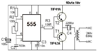
The circuit described is a high-frequency switching power supply designed for driving flyback transformers. The use of the 555 timer in astable mode allows for precise control over the frequency and duty cycle, which are critical parameters for efficient transformer operation. The careful selection of components, including the 2N3904 and 2N3906 transistors, provides a robust output stage capable of fast switching, essential for minimizing power losses and maximizing energy transfer to the transformer.
The snubber circuit is an important addition, as it mitigates voltage spikes that can occur during the switching process, which could otherwise damage sensitive components. The choice of the IRF840 MOSFET is particularly suitable due to its high voltage and current ratings, making it capable of handling the demands of the circuit while ensuring reliability under varying load conditions.
Adjustments to the circuit can be made by changing the values of the timing resistors and capacitors, allowing for flexibility in application, whether for high-frequency operations or lower frequency applications where larger capacitors are utilized. The design can accommodate various transformer types, making it a versatile solution for high-voltage applications, including the charging of capacitors and other devices requiring high voltage supply. Proper thermal management and component ratings should be considered to ensure long-term reliability and performance of the circuit. Many sites doesn`t provide circuits driving these transformers, they simply say that they are bad. I don`t agree. In fact I built this circuit. I spent a lot of time for finding resonant frequency (around 15Khz) and duty cycle. These transformers best work at around 90% duty cycle. You may notice corona breakdown at terminals and pfffff sound (as well as the ozone smell) when adjusting the off time trimmer to near 500-300 ohms. Of course it will work for other tipes of flyback as frequency and duty cycle have a large range. Frequency range can be increased using multiposition switch for other values of C3 capacitor, for example 2 nF for 80KHz-200000KHz, but didn`t found flybacks with so high resonant frequencies, in addition with higher values of c3, eg 200nF, 2uF the frequency will drop making possible the use of ignition coils, and rectified power transformers @50Hz to charge high voltage electrolitic caps at 300-400V).
Unfortunately my ignition coil died because insulation breakdown (too long drawn arcs). The 555 is wired as an astable and the capacitor is charged only through the 4, 7Kohm trimmer (notice the diode) and discharged only through the 2. 2 Kohm trimmer, making the duty cycle full adjustable. The square wave is then feed in a totem pole made up of a 2N3904 and a 2N3906, which are cheap, and easy to find.
The totem pole ensures the gate being charged and discharged very fast (approx 50nS i think). The IRF840 is a cheap (i found it for 4euros) reliable and powerful power mosfet, it has current capability of 8 A continuous and 32A pulse, 800V drain source voltage, protecting internal zener diode. There is a snubbing network to ensure that voltage spikes are kept low (unless the insulation of the transformer start to leak) protecting both transistors and 555 IC.
100 ohm is a compromise between decay time and voltage spike. 🔗 External reference
Related Circuits
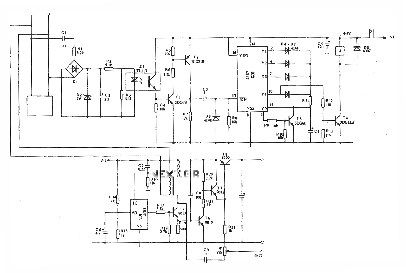
Optically isolated phone automatic recording interface circuit, IC3 voice module. The optically isolated phone automatic recording interface circuit is designed to capture audio signals from a telephone line while ensuring electrical isolation between the phone line and the recording device....
This 12V power inverter circuit can be utilized to power small devices that require 240 volts. It is particularly advantageous for operating 240-volt appliances using a 12-volt car battery. Unlike typical feedback oscillator inverters, this design employs a 555...
The circuit described can connect two telephones in parallel and function as a two-line intercom. Typically, a single telephone is connected to a telephone line. When another telephone is needed at a distance, a parallel line is utilized for...
Even if the circuit is simple, it complies with all conditions regarding distortion and frequency response. The input resistance is 250K ohms, and it can drive loads ranging from 100 ohms to 2K ohms. The described circuit is a fundamental...
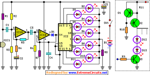
The basic circuit illuminates up to ten LEDs in sequence, following the rhythm of music or speech picked up by a small microphone. The expanded version can drive up to ten strips, each formed by up to five LEDs,...
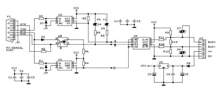
RS232 to RS485 Converter Circuit Schematic. RS232 to RS485 converters are primarily utilized in industrial and commercial settings. The RS232 to RS485 converter circuit is designed to facilitate communication between devices using different serial communication standards. RS232 is commonly found...