
Automatic telephone recording interface circuit optical isolation
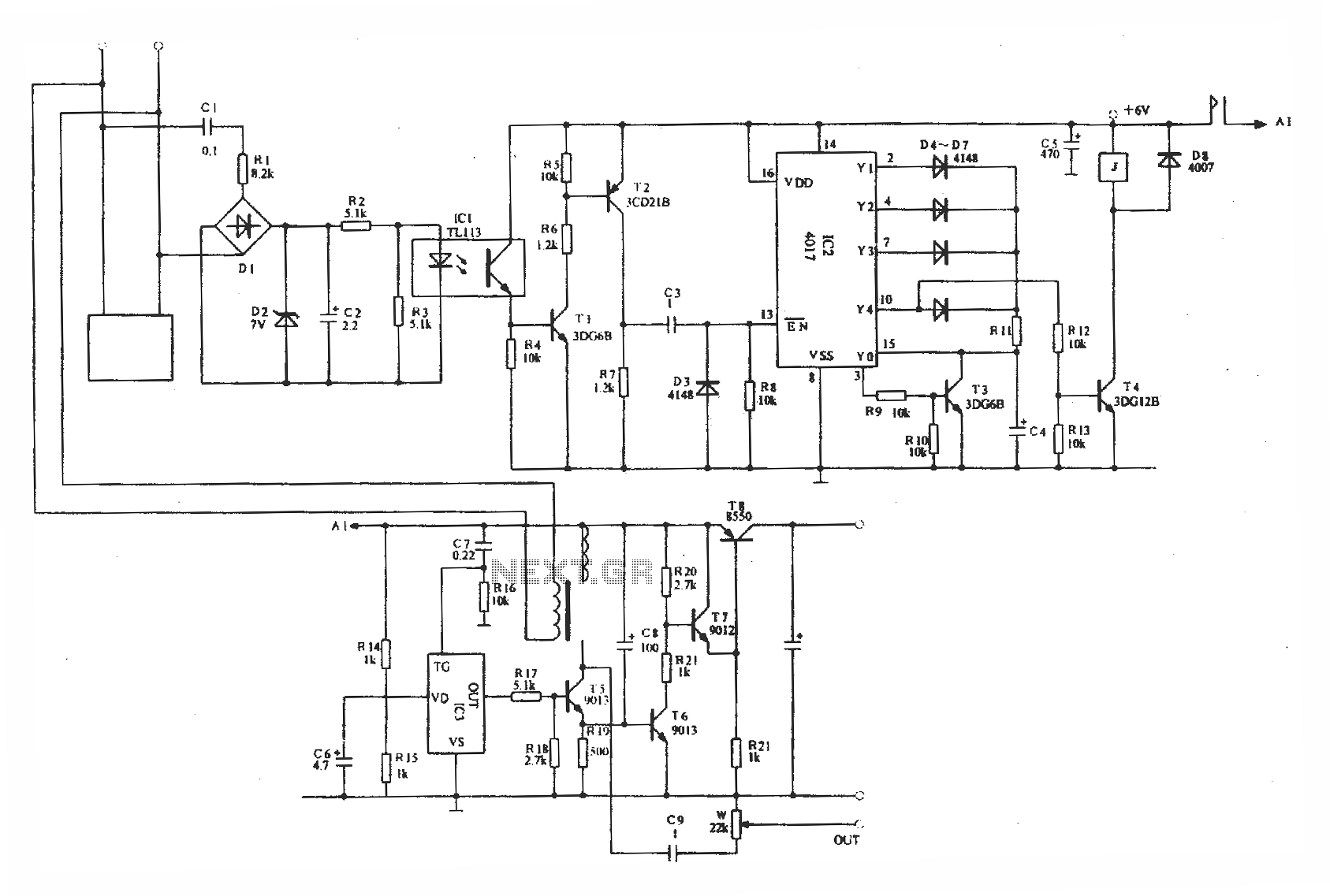
The optically isolated phone automatic recording interface circuit is designed to capture audio signals from a telephone line while ensuring electrical isolation between the phone line and the recording device. This circuit utilizes an IC3 voice module, which serves as the core component for audio processing and recording functionality.
The circuit typically includes an opto-isolator, which is crucial for protecting the recording equipment from high voltages present in telephone lines. This isolation prevents any potential damage to the recording device while allowing audio signals to pass through. The opto-isolator is connected to the telephone line, where it detects the audio signals and converts them into a form suitable for the voice module.
The IC3 voice module is responsible for capturing the audio signals transmitted through the opto-isolator. This module can be configured to record incoming and outgoing calls, depending on the design requirements. It may also include features such as adjustable gain control to optimize audio levels and filtering circuits to reduce noise and enhance sound quality.
Power supply considerations are essential in this circuit design. The voice module and opto-isolator must be powered adequately, often requiring a regulated power supply to ensure stable operation. Additionally, the circuit may incorporate capacitors and resistors to manage signal integrity and prevent distortion during the recording process.
Overall, this circuit provides a reliable solution for automatic phone recording, combining electrical isolation with efficient audio processing capabilities, making it suitable for various applications in telecommunications and audio recording systems.Optically isolated phone automatic recording interface circuit, IC3 voice module.
Related Circuits

A 555 timer (IC1) controls a 4017 CMOS decade counter. The first four outputs of the 4017 drive a CA3079 zero-voltage switch. Pin 9 of the CA3079 is utilized to inhibit output from pin 4, effectively disabling the stream...

This circuit is designed as a 10-channel LED sequencer with the addition of solid-state relays for controlling AC lamps. The circuit operates using relays. The relay depicted in the diagram is a Radio Shack 3 amp unit (part no....
This FM RF amplifier utilizes two transistors from Philips: the BLV 10 and the BLW 87. The two RF transistors are configured in a chic C arrangement, providing an overall gain of 21 dB (100 times) with an efficiency...
A circuit has been identified that integrates a voltage regulator and filter to isolate the voltage supplied by the receiver for powering an operational amplifier (op-amp) that drives a meter. Additionally, the circuit isolates the carrier frequency from the...
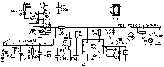
This circuit utilizes the KA2184 infrared receiver ASIC for an infrared remote control dimmer light application, as depicted in the schematic. The infrared signal is generated by a pulse generator using an NE555 timer integrated circuit. The NE555 produces...
The circuit diagram of an IC Controlled Emergency Light with Charger, also known as a 12V to 220V AC inverter circuit, is presented here. This circuit features automatic activation of the light during mains failure and includes a battery...