
Inverter circuit for florescents
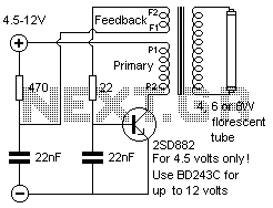
Bipolar NPN transistor: 2SD882 (or D882 as labeled)
Casing: TO126
Max. collector current: 3 Amperes
Max. total power: 10 Watts, while case is at 25 degrees Celsius
Transition frequency: 45 MHz
Max. collector capacity: 45 pF
hFE (current gain): 160 at 1 Ampere (typical value)
Bipolar NPN transistor: BD243C
Casing: TO220
Max. collector current: 6 Amperes
Max. total power: 65 Watts, while case is at 25 degrees Celsius
Transition frequency: 3 MHz
hFE (current gain): 30 at 300mA (minimum value)
In case you decided to build your own transformer, here are the instructions to create one:
First of all, you have to find a ferrite core transformer frame. It may be found in discarded rechargeable fluorescent lanterns (in this case it will be probably ready to use), fluorescent tube lights built to use in cars, at electronics stores, and in the energy saver lamps.
Following work describes the process to gain a ferrite core transformer from a dead energy saver lamp and give it a new life as the heart of the inverter. Please note that these lamps are in various sizes under various brands and it's important to get a transformer which is near or equal in size given above (25mm x 20mm x 5mm). Otherwise it may be difficult to fit the windings on it and performance may noticeably degrade.
Open the lamp and take out the PCB. Locate the ferrite core transformer and unsolder it. Detach the core parts and unwind the wires on the frame. Now you have an empty frame and two E-shaped core parts.
This inverter circuit is a simple yet effective design that utilizes a single transistor oscillator to drive a fluorescent tube. The operation begins with the application of a DC voltage to the primary winding of the transformer, which induces a magnetic field in the ferrite core. The feedback winding plays a crucial role in sustaining oscillation; as the magnetic field collapses, it induces a voltage in the feedback winding that turns the transistor on, allowing current to flow through the primary winding again.
The choice of transistor is significant, as it must handle the current and power requirements of the circuit. The 2SD882 is preferred for low-voltage applications (up to 4.5V), while the BD243C offers higher current and power handling capabilities for more robust applications. The oscillation frequency is determined by the inductance of the primary winding and the characteristics of the ferrite core, which should be selected to match the specified dimensions to ensure optimal performance.
For those constructing their own transformer, attention to detail during the winding process is critical. The number of turns for each winding (30 for primary, 15 for feedback, and 250 for secondary) directly affects the transformer’s efficiency and the inverter's overall performance. Proper insulation and securing of the windings will also minimize losses and enhance reliability.
Finally, when assembling the inverter, ensure adequate cooling for the transistor, as overheating can lead to failure. The circuit should be tested under controlled conditions to verify functionality before being used to power a fluorescent tube.This inverter is very easy to construct, reliable, and even powerful enough to light up a 15W florescent tube (if you cool your transistor well). The only hard-to-find piece of this baby is the so-called yellow inverter transformer. It's a miniature high frequency transformer that has a 25mm x 20mm x 5mm ferrite core, 30 turns of primary, 15 turns of feedback, and 250 turns of secondary all concentric, wound on plastic frame than wrapped with a 'yellow' adhesive tape.
If you can't find it in your local electronic shops then search for old portable rechargeble florescent lanterns since they have at least one yellow inverter. This is a single transistor oscillator circuit. Current passed through primary winding inducts a magnetic field to the core and the core gives the energy back to the feedback winding with a delay determined by the core material and windings. System then oscillates continuously on a frequency depending on this timing. You cannot use 2SD882 with voltages over 4.5 volts. It is only needed if you are going to feed the circuit with only 4.5 volts. Equivalent transistors may not work as good as 2SD882 (NEC Electronics, Japan). Characteristics are below : Bipolar NPN transistor : 2SD882 (or D882 as labeled) Casing : TO126 Max.
collector current : 3 Amperes Max. total power : 10 Watts, while case is at 25 degrees Celsius Transition frequency : 45 MHz Max. collector capacity : 45 pF hFE (current gain) : 160 at 1 Ampere (typical value) Bipolar NPN transistor : BD243C Casing : TO220 Max.
collector current : 6 Amperes Max. total power : 65 Watts, while case is at 25 degrees Celsius Transition frequency : 3 MHz hFE (current gain) : 30 at 300mA (minimum value) In case you decided to build your own transformer, here are the instructions to create one: First of all, you have to find a ferrite core transformer frame. It may be found in discarded rechargeable fluorescent lanterns (in this case it will be probably ready to use), fluorescent tube lights build to use in cars, at electronics stores, and in the energy saver lamps.
Following work describes the process to gain a ferrite core transformer from a dead energy saver lamp and give it a new life as the heart of the inverter. Please note that these lamps are in various sizes under various brands and it's important to get a transformer which is near or equal in size given above (25mm x 20mm x 5mm).
Otherwise it may be difficult to fit the windings on it and performance may noticeably degraded. Open the lamp and take out the PCB. Locate the ferrite core transformer and unsolder it. Detach the core parts and unwind the wires on the frame. Now you have an empty frame and two E shaped core parts. 🔗 External reference
Related Circuits
The calibration circuit operates in inject mode, generating a square wave output in the audio range, where power harmonics can be detected at several Hertz. In tracking mode, the amplifier detects non-linear operation by filtering a modulated RF signal...
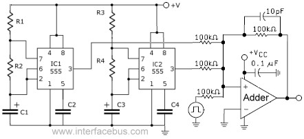
This circuit combines the outputs from two distinct 555 multivibrators using a summing operational amplifier (Op Amp). It serves to illustrate an alternative implementation of a 555 timer, with most background calculations addressed in other sections. The standard configuration...
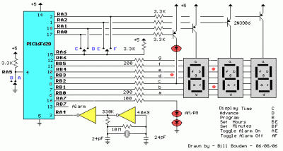
This clock timer utilizes a PIC16F628 microcontroller to display a 3.5-digit time format and control an external load. It is programmable to time intervals from 1 to 59 minutes. The clock features a calendar that accounts for leap years...
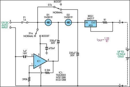
This circuit is designed to charge between one and twelve NiCd cells using a car battery. When switch S1 is in the "normal" position, it can charge up to six cells. The LM317 regulator functions as a simple current...
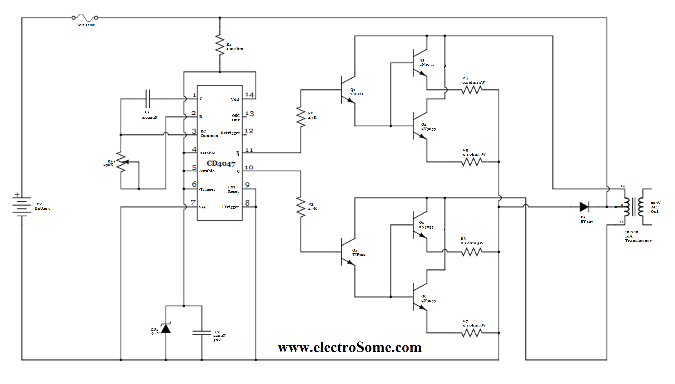
For basic requirements, square wave inverters can be utilized as they are simple, low-cost, and easy to construct. However, pure sine wave inverters are preferred for driving inductive loads. This document discusses a simple low-power square wave inverter using...
The circuit operates by monitoring the water level in a tank. When the water level falls below a specified point (F), the RS flip-flop (F2) is activated, producing a high Q output that energizes a relay to start the...