
LED Boost converter Joule Thief circuit
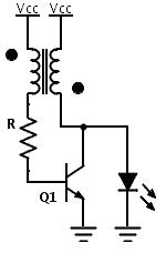
The described boost circuit operates on the principle of raising the voltage from a low input level to a higher output voltage sufficient to drive a 3 V LED. The circuit's core component, a transistor, functions as a switch, controlling the current flow through the transformer. When the transistor is turned on, current flows through the primary winding of the transformer, creating a magnetic field. When the transistor switches off, the magnetic field collapses, inducing a voltage in the secondary winding of the transformer.
The use of a 1:1 turns ratio transformer is critical; it allows the circuit to effectively transfer energy from the primary to the secondary winding without significant losses. However, the output voltage is influenced by the rate of change of the magnetic field and the load connected to the output. The resistor in the circuit plays a vital role in limiting the current through the transistor, ensuring it operates within safe limits and preventing damage.
Modifications to the circuit, such as increasing the number of turns in the transformer or adjusting the resistor value, can impact the performance. Adding turns to the transformer can increase the output voltage, but it may also affect the efficiency and response time of the circuit. Similarly, altering the resistor value can change the operating point of the transistor, which may either enhance or degrade the circuit's performance.
Understanding these dynamics is essential for optimizing the circuit for specific applications, such as powering LEDs from low-voltage sources. Further experimentation and analysis are recommended to achieve the desired performance while ensuring reliability and efficiency.In the past I already tested a nice boost circuit that allows us to power a 3 V LED with a discharged battery (around 1 V or less). This circuit uses just one transistor, one resistor and a small transformer (1:1 ratio). The theory behind this circuit seems to be obscure as we can find lot of comments and questions like: can I add turns, can I increase the resistor 🔗 External reference
Related Circuits
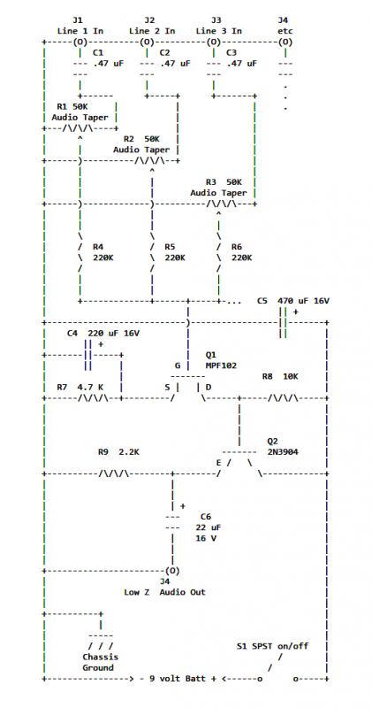
If two of these circuits are made in the same enclosure for stereo, then there can be a single power supply to run both of them. There should be a resistor in series with the incoming 9V+ lead so...
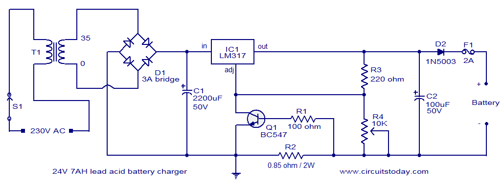
This lead-acid battery charger circuit is designed based on a request from Mr. Devdas C. His requirement was for a circuit that could charge two 12V/7AH lead-acid batteries connected in series. He did not specify the number of cells...
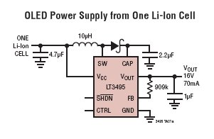
The LT3495, LT3495B, LT3495-1, and LT3495B-1 are low-noise boost converters equipped with an integrated power switch, feedback resistor, and output disconnect circuitry. These devices manage power delivery by adjusting both the peak inductor current and the switch off-time, resulting...
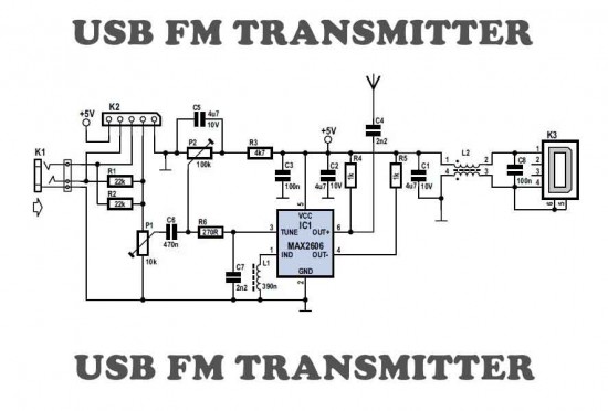
This is a simple USB FM transmitter designed to play audio files from an MP3 player or computer on a standard VHF FM radio. The USB FM transmitter operates by converting audio signals from a digital source, such as an...
Gates U1-a and U1-b of the 4093 quad 2-input NAND Schmitt trigger are connected in variable, low-frequency square-wave oscillator circuits. The output of gate U1-a is connected to one of the inputs of gate U1-b. The square-wave output of...
This circuit produces the famous Big Ben sound. It produces the "ding dong" sound when switched ON. Basically, the circuit alternates between two frequencies which are adjustable. This produces the "ding-dong" sound. The first IC (left) oscillates at about...