
FM Audio Transmitter Circuit
This FM low-power transmitter circuit operates within the designated FM band and is suitable for short-range audio transmission applications. The use of BC548 transistors allows for effective amplification of the audio signal, enabling the circuit to transmit clear audio frequencies. The ECM microphone serves as the audio input, converting sound waves into electrical signals, which are then amplified by the transistors.
The coil L1 is a critical component in determining the operational frequency of the circuit. The seven turns of wire wound on a plastic former create an inductor that, in combination with the tuning slug, allows for precise tuning within the desired frequency range. The tuning slug's position can be adjusted to fine-tune the circuit to specific frequencies, which is essential for ensuring compliance with local regulations and minimizing interference with other radio services.
The choice of antenna is also significant; a simple wire antenna is sufficient for this low-power application. However, careful attention must be paid to the length of the antenna, as exceeding two feet can lead to reduced performance due to the damping of oscillations.
For construction, while a printed circuit board (PCB) is recommended for best practices in RF circuit design, using veroboard is a viable alternative. It is crucial to maintain short lead lengths and to break tracks at strategic points to minimize unwanted capacitance and inductance, which can adversely affect circuit performance.
Overall, this circuit serves as a practical example of a low-power FM transmitter, suitable for hobbyist applications while adhering to legal constraints regarding radio transmission.It is illegal in most countries to operate radio transmitters without a license so take care with transmitter circuits. This FM low power circuit may be tuned to operate over the range 87-108 MHz band II, with a range of 20 or 30 metres.
Active components in this audio transmitter circuit are BC548 transistors. Although not strictly RF transistors , they still give good results. I have used an ECM Mic (Voice FM ) insert from Maplin Electronics, order code FS43W. It is a two terminal ECM, but ordinary dynamic mic inserts can also be used, simply omit the front 10k resistor. The coil L1 was again from Maplin, part no. UF68Y and consists of 7 turns on a quarter inch plastic former with a tuning slug. The tuning slug is adjusted to tune the transmitter. Actual range on my prototype tuned from 70MHz to around 120MHz. The aerial is a few inches of wire. Lengths of wire greater than 2 feet may damp oscillations and not allow the circuit to work. Although RF circuits are best constructed on a PCB, you can get away with veroboard, keep all leads short, and break tracks at appropriate points.
🔗 External reference
Related Circuits
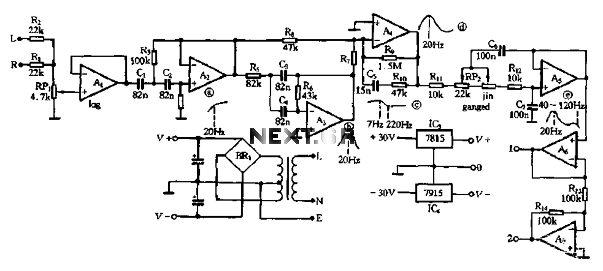
This electronic bass equalizer circuit utilizes two quad operational amplifiers, specifically the TL084 high-speed operational amplifier. The circuit includes left and right channels that are mixed through resistors R1 and R2, and features a total bass level adjustment potentiometer...

This is a simple lamp flasher circuit that utilizes only three components (a capacitor, a relay, and a resistor) in addition to the lamp. The operation of the circuit is straightforward. When power is turned on, the capacitor C1...

This is a stereo amplifier circuit diagram. The amplifier will produce stereo output channels with a power audio output that can reach up to 70W for each channel. The amplifier is built using the STA550 chip from STMicroelectronics. It...

The application involves observing the light pulse emerging from a thick specimen after transillumination by a laser pulse. Pulses derived from the laser source are amplified using a Video Amplifier LM733. The reference level is set to 1 V...
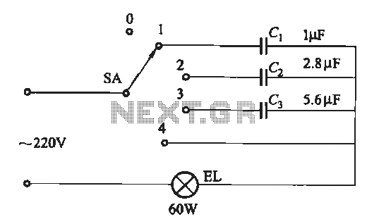
A dimming circuit capacitor circuit is illustrated in Figure 2-63. When the switch SA is moved from position "1" to "3," the capacitance increases in ascending order, resulting in the light bulb brightness also increasing correspondingly. When SA is...

This circuit serves as a decorative element or indicator, featuring adjustable flashing or dancing speeds of LEDs and the ability to create various light patterns. It consists of two astable multivibrators: one formed by transistors T1 and T2, and...