
FM Beacon Transmitter circuit
The described circuit functions as a simple FM transmitter that operates within the FM band, specifically designed for applications such as remote control or security signaling. The core of the circuit utilizes a 555 timer IC configured in astable mode, generating a square wave output at approximately 600 Hz. This output is used to modulate the frequency of a Hartley oscillator, which is the primary component responsible for generating the radio frequency signal.
The Hartley oscillator is designed using a tapped inductor and a capacitor, where the inductor is custom-made by winding it around a bolt and then adjusting its length for fine-tuning the frequency. The oscillator's output frequency is adjustable, allowing it to be centered around 98 MHz, which is within the FM broadcast band. The tuning capability is enhanced by the use of a varactor diode (1N914 or 1N4148), which alters its capacitance in response to the applied voltage from the 555 timer, thus enabling frequency modulation at the audio rate.
The circuit draws a modest current of 30 mA from a power supply ranging from 6 to 9 volts, making it suitable for battery operation. The design incorporates a JFET buffer stage to ensure that the oscillator's performance is not adversely affected by the characteristics of the antenna. This isolation helps maintain a stable output frequency regardless of variations in antenna length or positioning.
Fine adjustments to the oscillator frequency can be achieved by varying a 200-ohm resistor in series with the power supply, allowing for precise tuning to the desired frequency. The circuit's effective transmission range is approximately 100 yards, making it practical for various low-power transmission applications. Proper care should be taken to ensure compliance with local regulations regarding FM transmission to avoid interference with licensed broadcasts.This circuit will transmit a continuous audio tone on the FM broadcast band (88-108 MHz) which could used for remote control or security purposes. Circuit draws about 30 mA from a 6-9 volt battery and can be received to about 100 yards. A 555 timer is used to produce the tone (about 600 Hz) which frequency modulates a Hartley oscillator.
A second JFET transistor buffer stage is used to isolate the oscillator from the antenna so that the antenna position and length has less effect on the frequency. Fine frequency adjustment can be made by adjusting the 200 ohm resistor in series with the battery. Oscillator frequency is set by a 5 turn tapped inductor and 13 pF capacitor. The inductor was wound around a #8 X 32 bolt (about 3/16 diameter) and then removed by unscrewing the bolt. The inductor was then streached to about a 3/8 inch length and tapped near the center. The oscillator frequency should come out somewhere near the center of the band (98 MHz) and can be shifted higher or lower by slightly expanding or compressing the inductor.
A small signal diode (1N914 or 1N4148) is used as a varactor diode so that the total capacity in parallel with the inductor varies slightly at the audio rate thus causing the oscillator frequency to change at the audio rate (600 Hz). The ramping waveform at pins 2 and 6 of the timer is applied to the reversed biased diode through a large (1 Meg) resistor so that the capacitance of the diode changes as the ramping voltage changes thus altering the frequency of the tank circuit.
Alternately, an audio signal could be applied to the 1 Meg resistor to modulate the oscillator but it may require an additional pullup resistor to reverse bias the diode. The N channel JFET transistors used should be high frequency VHF or UHF types (Radio Shack #276-2062 MPF102) or similar.
🔗 External reference
Related Circuits
Visit eBid United Kingdom, the online marketplace without fees - buy and sell today. eBid United Kingdom serves as an online marketplace that facilitates buying and selling transactions without imposing fees on its users. This platform offers a user-friendly interface...
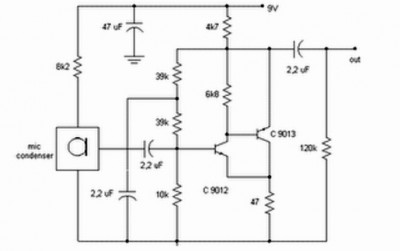
Preamp circuits are used in front of an RF oscillator to create an RF transmitter that is highly sensitive to sound. A microphone preamp must provide stable gain. Preamp circuits play a crucial role in the functioning of RF transmitters...
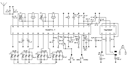
The TEA5711 datasheet indicates that essential functions, including the AM and FM front end, AM detector, and FM stereo output stages, are integrated within the TEA5711 AM/FM stereo radio circuit. The accompanying circuit diagram illustrates the TEA5711T in conjunction...
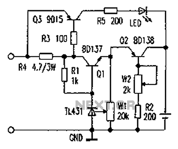
As illustrated in the figure, the lithium battery charging control board employs a constant current charging mechanism. The components Q1, R1, W1, and TL431 form a precision adjustable voltage regulator circuit. The components Q2, W2, and R2 create an...
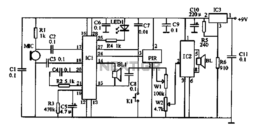
Doppler effect sensor N1 (RD627), operational amplifier N2 (LM358), and a special integrated circuit for imitating dog barking (N3, KD5608) are utilized along with other components. When there is no activity detected in the monitoring area by N1, the...
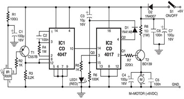
The following circuit illustrates an Infrared Toy Car Motor Controller Circuit Diagram. This circuit is based on the 4017 IC. Features: operating at .. The Infrared Toy Car Motor Controller Circuit utilizes a 4017 Decade Counter IC, which is integral...