
Simple PreAmp MIC Circuit

Preamp circuits play a crucial role in the functioning of RF transmitters by amplifying audio signals before they are modulated onto a radio frequency carrier. The primary function of a microphone preamp is to increase the amplitude of weak audio signals generated by microphones, ensuring that the subsequent RF circuitry receives a strong and clear input.
In designing a preamp circuit for an RF transmitter, several key components are typically included. These may consist of operational amplifiers (op-amps), resistors, capacitors, and sometimes inductors, depending on the required frequency response and gain characteristics. The op-amp serves as the core amplification element, where its gain can be adjusted through feedback resistors to achieve the desired level of amplification while maintaining low noise levels.
Stability in gain is critical for a microphone preamp, as variations can lead to distortion or loss of audio fidelity. To ensure stable gain across a range of input levels, the circuit may incorporate negative feedback mechanisms. Additionally, proper power supply decoupling is essential to minimize noise and interference, which can adversely affect the performance of the RF transmitter.
The preamp circuit should also be designed to handle the frequency response of the audio signals, typically ranging from 20 Hz to 20 kHz, while ensuring that the output signal is compatible with the RF oscillator's input requirements. Filtering components may be added to eliminate unwanted frequencies and improve the overall signal quality.
In summary, the design of a preamp circuit for an RF transmitter involves careful consideration of component selection, gain stability, and frequency response to achieve optimal performance in sound sensitivity and clarity.preamp circuits use infront an RF oscilator to make an RF transmitter that is very sensitive to sound. A microphone preamp must provide stable gain. 🔗 External reference
Related Circuits

This page presents a replacement circuit for the LM3909 LED Flasher/Oscillator utilizing discrete components. The circuit functions similarly to the integrated LM3909 but features minor variations in the component values used. Although the LM3909 is still available, it tends...
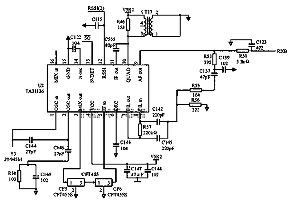
As illustrated in the figure, Vcc is the power supply for the circuit. Upon receiving the initial signal, the frequency is adjusted to 21.7 MHz. This frequency is subsequently enhanced through two crystal filters to improve the selectivity of...
This is a car alarm simulator that uses an LED as a simulation output. This simple circuit can indicate whether a car is running or not by detecting the voltage difference when the car is on or off. This...
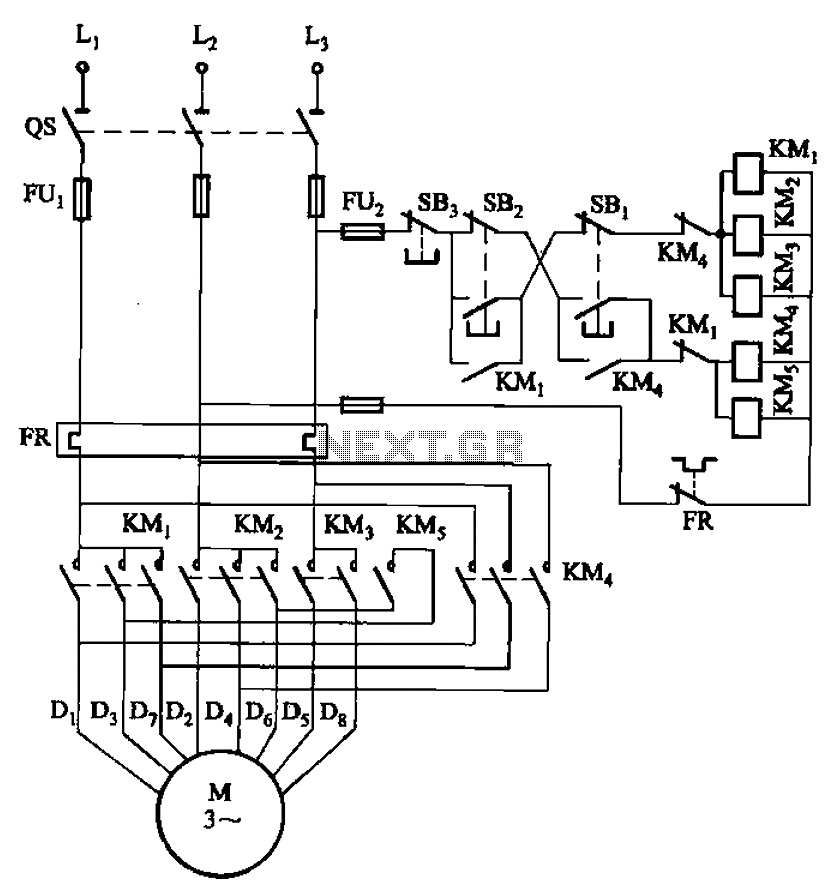
The circuit illustrated in Figure 3-104 features SB2, which functions as the low-speed operation button, and SBi, which serves as the high-speed operation button. The circuit design utilizes two distinct operational buttons, SB2 and SBi, to control the speed of...
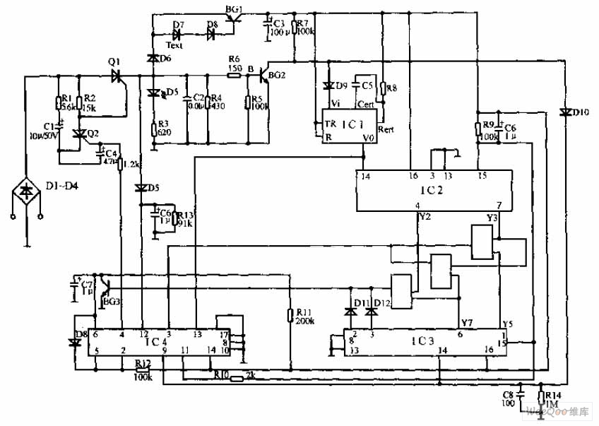
The pulse telephone 160 168 controller circuit is depicted above. This controller can be installed either on the telephone or on the switchboard of the trunk line. It effectively prevents unauthorized dialing of numbers 160 and 168. Diodes D1...
This circuit design features a modular arrangement that enables users to select only the modules best suited to their needs, allowing for the construction of a chain ranging from one to five modules in length. For those seeking a...