
Fuel Tank Pressure Sensor Circuit with explanation

The fuel tank pressure sensor is a critical component in the vehicle's evaporative emission control system. It provides real-time data regarding the pressure conditions within the fuel tank, which is essential for maintaining optimal performance and compliance with emissions regulations. The sensor operates by varying its output voltage in response to changes in fuel tank pressure, which is an indication of the presence of fuel vapors and potential leaks in the system.
In normal operation, when the fuel tank is at atmospheric pressure, the sensor outputs a low voltage signal, typically around 0.1 volts. As the fuel tank experiences a vacuum condition, which may occur during fuel evaporation or due to temperature changes, the sensor's output voltage increases, potentially exceeding 4.0 volts. This voltage variation is sent to the vehicle control module (VCM), which processes the information to determine if the system is functioning correctly.
The control module employs this data during the EVAP diagnostic routine to assess the integrity of the fuel system. If the module detects a significant drop in voltage, indicating vacuum decay, or an excessively high voltage, suggesting an over-vacuum condition, it triggers appropriate diagnostic trouble codes (DTCs) for further investigation. This functionality is vital for ensuring that the vehicle meets emission standards and operates efficiently without releasing harmful vapors into the atmosphere.
Overall, the fuel tank pressure sensor and its integration with the control module play a crucial role in the vehicle's emissions management system, contributing to both environmental protection and vehicle performance.The control module monitors the fuel tank pressure (FTP) sensor signal in order to detect vacuum decay and excess vacuum during the enhanced evaporative emission (EVAP) diagnostic. The Fuel Tank Pressure Sensor responds to changes in the fuel tank pressure or vacuum. This information is used in order to detect vacuum decay or an excessive vacuum d uring EVAP diagnostic routing. The fuel tank pressure sensor signal voltage to the VCM varies from a minimum of about 0. 1 volts with pressure in the fuel tank to above 4. 0 volts with a high vacuum in the fuel tank. Disclaimer All files are found using legitimate search engine techniques. This site does not and will not condone hacking into sites to create the links it list. We will and do assume that all links found on the search engines we use are obtained in a legal manner and the webmasters are aware of the links listed on the search engines. If you find a URL that belongs to you, and you did not realize that it was "open to the public", please use the report button to notify the blogmaster of your request to remove it or it will remove within 24 hours.
This is not an invitation for webblog haters to spam with requests to remove content they feel that is objectionable and or unacceptable. Proof of URL ownership is required. NOTICE: This Blog Has Already Been Reviewed And Accepted By Blogger. com 🔗 External reference
Related Circuits
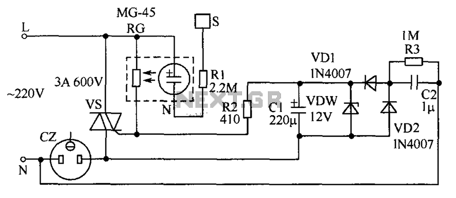
The circuit operates by detecting a finger touch on a metal sheet (S), which activates a neon tube light (N). The combination of the neon tube and a photoresistor (RG) acts as an optocoupler, reducing the resistance of RG....
The primary objective is to present the circuit diagram and describe the software utilized. A UDP application is employed to transmit commands to the microcontroller, which subsequently activates or deactivates the relay. It is anticipated that TCP implementation could...
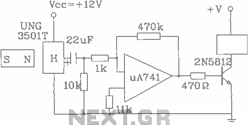
The UGN-3501T Hall sensor features a highly sensitive counter circuit diagram, allowing it to detect very small changes in magnetic fields. This capability enables the detection of ferrous metals. Utilizing this characteristic, it can be employed to count loads....
Unfortunately, there is no breadboard available for testing; however, modifications can be made to the PCB. The 1K potentiometer has been removed until the strobe functionality can be established. The circuit in question appears to involve a strobe light mechanism,...
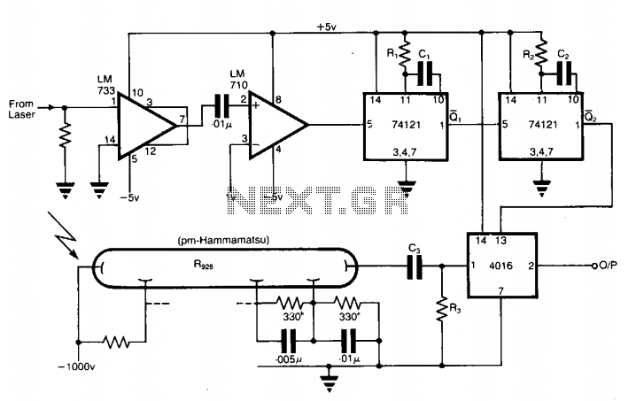
The application involves observing the light pulse emerging from a thick specimen after transillumination by a laser pulse. Pulses derived from the laser source are amplified using a Video Amplifier LM733. The reference level is set to 1 V...
Dark Activated Switch or Porch Light Switch. This circuit activates a relay when the light level drops below a preset threshold. The light sensitivity can be adjusted using variable resistor VR1, and the relay contacts can control an external...