
fm if mw radio receiver circuit using la1260 ic
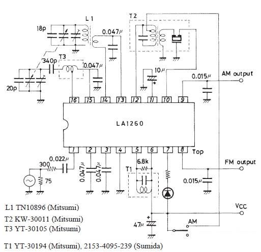
The LA1260 IC is designed to facilitate the construction of efficient AM and FM radio receivers, making it an ideal choice for electronic hobbyists and professionals alike. Its high S/N ratio ensures clear audio reception, which is particularly beneficial in areas with weak signal strength. The built-in low-level AM oscillator with ALC enhances the receiver's ability to handle varying signal levels, ensuring consistent performance across different frequency bands.
The separation of components within the circuit is critical for maintaining performance integrity. The AM local oscillation coil and antenna circuit should be distanced from one another to reduce interference and optimize the receiver's sensitivity. The layout should be designed to minimize crosstalk between the AM oscillation injection pin and the RF input pin, as proximity can lead to signal degradation and affect overall performance.
The inclusion of an LED tuning indicator allows users to easily determine when the receiver is properly tuned to a station, enhancing usability. The independent output pins for FM and AM signals provide flexibility in circuit design, allowing users to connect to various audio processing units or amplifiers as needed.
In terms of power requirements, the specified operating voltage range of 3 to 8 volts DC provides versatility for different applications, enabling the circuit to be powered by various sources, including batteries or regulated power supplies. The recommended 4.5 volts DC serves as an optimal operating point, balancing performance and power consumption.
Overall, the LA1260-based FM IF MW radio receiver circuit presents a robust solution for radio reception, combining advanced features with practical design considerations to deliver a reliable and high-quality audio experience.As you can see in this FM IF MW radio receiver circuit schematic the LA1260 ic can be used in AM FM radio receiver electronic projects. LA1260 has integrated in the package many functions and features that are needed for radio receiver applications.
high S/N : FM 81dB, AM 53dB ;low-level AM oscillator with ALC MW 130mV SW 70 mV to 90 mV (7MHz) (2 4MHz) ;less AM whistle interference : whistle 1% at input 100dB/m. ;on-chip LED tuning indicator driver ;on-chip FM/AM selector; independent FM/AM output pins. The AM local oscillation parts, AM local oscillation coil, and antenna circuit parts such as bar antenna must be separated from each other as far as possible to prevent Qs from worsening. Pin 16 (AM oscillation injection pin) and pin 14 (RF input pin) must be separated from each other. The recommended power supply for this radio receiver circuit is 4. 5 volt DC, but the LA1260 ic accepts an input voltage range from 3 to 8 volts DC. 🔗 External reference
Related Circuits
This active subwoofer filter circuit is a 24 dB per octave filter with a Bessel characteristic and a cutoff frequency of 200 Hz. It is suitable for those experimenting with audio circuits in the subwoofer range, as all audio...
There is a requirement for a compact flashlight to illuminate small text on integrated circuits (ICs) and provide better visibility when examining disassembled components. The flashlight should have a long battery life while avoiding excessive battery consumption, such as...
For use with low-power transmitters that require a positive keying voltage. The transistors Q1, Q2, and Q3 are configured as a switching amplifier. When the key is pressed, the collector of Q3 is pulled to ground, which activates Q5...
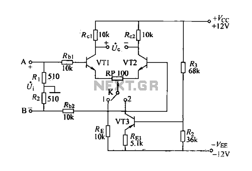
The differential amplifier is known for its stability and zero drift suppression. The circuit, as illustrated, utilizes two identical transistors, VT1 and VT2 (both 3DG6). The reference values for the component parameters are depicted in the figure. The circuit...
Figure 3-142 illustrates the reel control circuit. The coiler is utilized for winding plastic banding, such as grafting tape, onto a plastic reel. To prevent the plastic tape from being pulled off due to its low tensile strength, the...
The circuit depicted in Figure 3-69 is designed for applications requiring frequent timing control for motor reversing operations. In this configuration, thyristors V1, V2, and V7 are utilized for positive control of motor rotation, while thyristors V3, V4, V5,...
Warning: include(partials/cookie-banner.php): Failed to open stream: Permission denied in /var/www/html/nextgr/view-circuit.php on line 713
Warning: include(): Failed opening 'partials/cookie-banner.php' for inclusion (include_path='.:/usr/share/php') in /var/www/html/nextgr/view-circuit.php on line 713