
Qrp Sidetone Generator Code Practice Oscillator Circuit
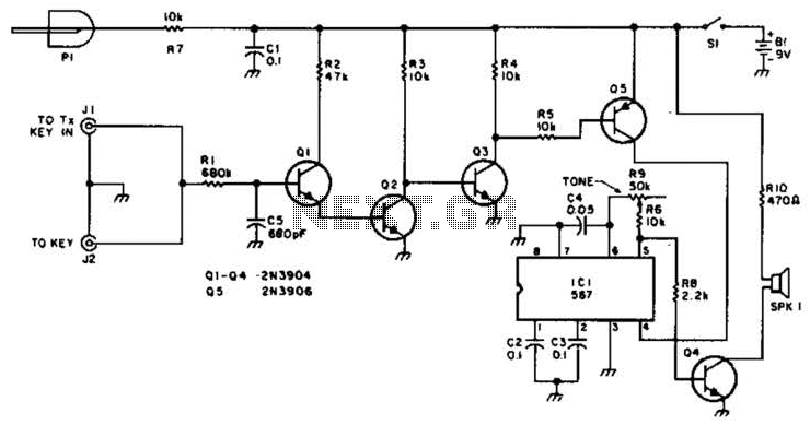
The described circuit serves as a low-power transmitter interface, designed to operate with a positive keying voltage. The primary components, Q1, Q2, and Q3, are arranged in a switching amplifier configuration. This arrangement allows for efficient control of the circuit's power state based on the keying action.
When the key is engaged, it causes the collector of transistor Q3 to be pulled down to ground potential. This action activates transistor Q5, which acts as a further switch in the circuit. The activation of Q5 results in the powering of IC1, which is an audio oscillator. The audio oscillator generates a tone or signal that can be utilized for various applications, such as signaling or sound generation.
Transistor Q4 is employed to drive the speaker, allowing the audio output generated by IC1 to be converted into sound waves. This configuration is particularly useful in applications such as code practice oscillators, where the generated audio signal can be used for training purposes in Morse code transmission.
For enhanced functionality, the circuit includes provisions for additional components. In the case of a code practice oscillator, inserting PI and J1 into the circuit allows for further customization and expansion. Additionally, a key can be connected to J2, providing the user with a straightforward interface for initiating the audio output.
Overall, this circuit design is optimized for low-power applications, ensuring efficient operation while providing the necessary features for audio generation and transmission in various electronic projects. For use with low-power transmitters with a positive keying voltage. Q1/Q2/Q3 form a switching amplifier. When the key is pressed, the collector of Q3 goes to ground, turning on Q5 and activating IC1, an audio oscillator. Q4 drives the speaker. For use as a code practice oscillator, insert PI and J1 and a key in J2. 🔗 External reference
Related Circuits
This discussion covers three different Xenon flashing circuits from disposable cameras. From these circuits, unique techniques not found in any theoretical literature will be presented. The first circuit consists of six building blocks. An old disposable flash camera and...

This is the initial Instructable and the first attempt at a large electronics project. The circuit has been designed from scratch and is being made available. The presented project involves the design of an electronic circuit that has been developed...
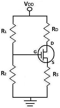
During DC analysis, all AC voltage sources are removed from the circuit since they are AC sources. DC analysis focuses solely on DC sources. Additionally, all capacitors are removed because, in a DC context, capacitors act as open circuits....
Displeased with your younger brother's choice of TV channels? Frustrated by the volume level your spouse sets on the stereo? Looking to create a bit of mischief? This circuit effectively jams most infrared (IR) remote signals. It emits a...
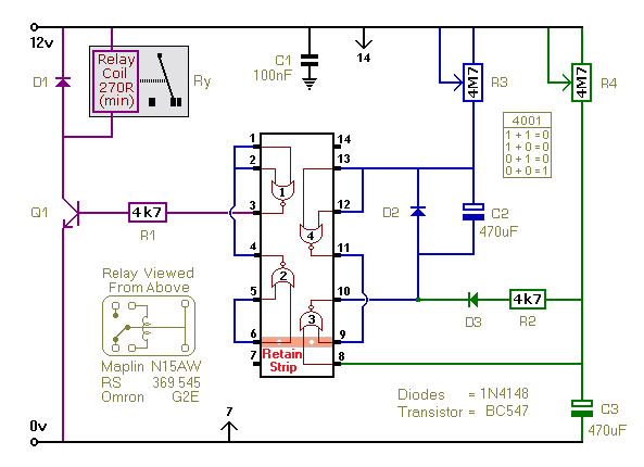
This timer utilizes a basic monostable circuit. The duration for which the relay remains energized, referred to as the ON period, is regulated by the resistor R3 and capacitor C2. Conversely, the duration for which the relay remains de-energized,...
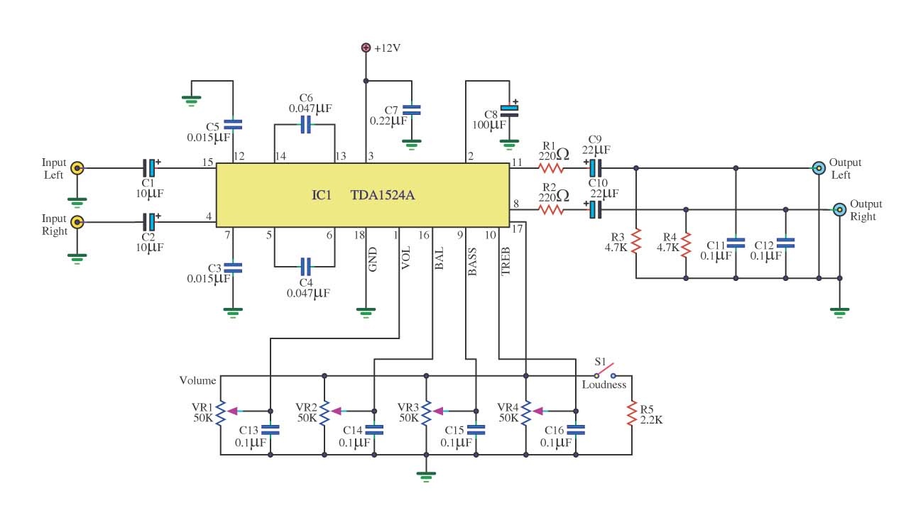
This is a simple tone control circuit using the TDA1524A, which is a key component in this IC chip diagram from Philips. The circuit allows for tone control adjustments such as bass, treble, and balance, enabling users to fine-tune...