
FM Micro-Transmitter Bug Surveillance Circuit
The emitted signal is FM-modulated, meaning the amplitude of the carrier wave remains constant while its frequency varies according to the audio signal's amplitude. The transmission frequency can be adjusted between 88-108 MHz using a capacitive trimmer (C1). By altering the coil's turns or spacing, the transmitter can be tuned to 85 or 110 MHz for added secrecy. The circuit includes a microphone, a microphone preamplifier (TR2), and the primary stage (TR1), which functions as the oscillator.
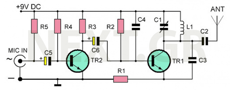
The condenser microphone, with its high sensitivity, generates an electrical signal when sound waves cause its movable diaphragm to vibrate. This signal is fed through C5 to the input of TR2, an amplifier. Resistor R4 ensures proper biasing of TR1 (2N2222), while R3 serves as its load resistance. The acoustic signal is amplified at the oscillator's input via C4, with C6 blocking DC voltage. The base of TR1 is biased by R2, and R1 stabilizes the transistor's operating point as an oscillator. Capacitor C3 provides feedback for oscillations, while the resonant circuit formed by L1 and C1 maintains a stable operating frequency. Capacitor C2 decouples the circuit, allowing only the modulated signal to radiate.
The transmitter requires a 9 to 15V DC power supply, typically a 9-volt battery providing 12 to 15 hours of operation. For extended use, multiple batteries can be connected in parallel. The transmission range is influenced by the tuned frequency and the antenna used, which can be a 65 cm wire or a standard dipole.
Bug Transmitter Characteristics:
- Operating Voltage range: 9-16V DC
- Current Consumption: 30 mA max
- Operating Frequency range: 88-108 MHz
- Modulation: FM
- Power Output: 0.2 Watt
- Transmitting Distance range: 100-300 m
Components:
- Resistors: R1 = 180Ω, R2 = 12KΩ, R3 = 1KΩ, R4 = 1MΩ, R5 = 39KΩ
- Capacitors: C1 = 7-35pF trimmer, C2 = 8.2pF ceramic, C3 = 8.2pF ceramic, C4 = 1.5pF ceramic, C5 = 1μF/25V electrolytic, C6 = 1μF/25V electrolytic
- Transistors: TR1 = 2N2222 NPN, TR2 = BC547 or BC548 NPN
- Coil: L1 = 4 turns, diameter of 6 mm
- Microphone: Condenser Microphone
- Power Supply: 9V Battery Clip
Construction involves soldering components onto a PCB, starting with resistors, followed by capacitors, and then transistors, ensuring correct polarity for electrolytic capacitors. After assembly, a visual inspection is essential before connecting the battery. Tuning the transmitter requires finding a clear frequency on the radio and adjusting the trimmer until interference disappears. It is crucial to keep the radio at a distance during tuning to avoid confusion from harmonics.
In case of malfunction, disconnect the power supply and carefully check component placement, polarity, and possible short circuits. Ensure all connections are secure and components are functioning correctly.The transmitter we recommend to build is quite simple. It can even be built by a beginner. However, unlike the ease of construction and its small size, it is almost certain that it will impress you with its outstanding performance. Its autonomy is 12-15 hours, with a 9 volt battery and its range is from 100 to 300 meters depending on the emission conditions.
It's intended for experimentation and amateur use, but it has countless applications limited only by your imagination. It is, for example, suitable for situations where you would like to impress your friends who are listening at short distances to the frequency you are broadcasting.
You can build two such transmitters and use two common FM radios as receivers to obtain a wireless and inexpensive intercom system. You can even incorporate this device into your smartphone, TV, or any other device to make a wireless connection between the device and the stereo of your home or your car.
Finally, because it uses a very sensitive microphone that can even capture whispering, it is sure that if you put it in a room, you can hear all the conversations that take place inside it. In other words, it can be used as a spy/surveillance transmitter.
How the circuit work
The emitted signal is FM-modulated, which, as you know, means that the amplitude of the carrier wave, remains constant while its frequency, varies according to the amplitude of the audio signal. This term FM is the initials of the words Frequency Modulation.
The transmit frequency can be set between the 88-108MHz frequencies, giving you the ability to select whichever you want or whichever is clearer.
This setting is quite simple and its done from the C1 capacitive trimmer.
If you want, by changing the turns or the distance between the turns of the coil, to exceed the FM broadcasting band and you can tune the transmitter to 85 or 110MHz. This is where we want to have secrecy in our broadcasts. So a small operation on the transmitter coil and on the radio (in the trimmers of the local oscillator and in the trimmer of the antenna) can provide you with the secrecy you may want.
;-)
Observing the theoretical design, we distinguish the microphone, the microphone preamplifier (TR2) and the primary stage (TR1) of the transmitter, which is also the oscillator of the circuit.
The microphone is a condenser type, which is essentially an air condenser, with two reinforcements of which one is fixed and the other is movable. The movable reinforcement consists of a thin film, which is pulsed when the sound waves drop over it, thus decreasing the capacity of the capacitor, thereby generating an electrical signal.
The main feature of the condenser microphones is their great sensitivity, which is why we chose it for this circuit.
The signal produced by the microphone is driven through the C5 at the input (base) of TR2, which is an amplifier in a common transmitter. Resistor R4 regulates correct polarization of TR1 (2N2222) and R3 is the resistance of its load.
The acoustic signal is amplified by means of the electrolytic capacitor C4 (1μf) at the input of the oscillator.
Capacitor C6 prevents the DC voltage passing to the oscillator input, while the base of the TR1 transistor is biased by R2 resistor.
The resistor Rl polarizes and stabilizes the operating point of the transistor working as an oscillator, while the capacitor C3 generates the necessary feedback to maintain the oscillations.
The resonant circuit L1-C1 maintains these oscillations without any change in operating frequency. C2 is a decoupling capacitor and allows only the radiation of the modulated signal to pass without continuous voltages.
The power supply of the transmitter requires a voltage of 9 to 15V DC from a stabilized power supply.
In practice, the power supply can be made from a common 9Volt battery that provides 12 to 15 hours of autonomy. If you want more autonomy you only have to connect two or more batteries in parallel.
The transmission range depends on:
a) The frequency you will tune the transmitter and
b) The antenna you will use, which may be a piece of wire about 65 cm long or even a common broadcast dipole.
Bug Transmitter Characteristics
- Operating Voltage range: 9-16VDC
- Current Consumption: 30mA max
- Operating Frequency range: 88-108MHz
- Modulation: FM Power Output: 0,2Watt
- Transmitting Distance range: 100-300m
Components
R1 = 180Ω, R2 = 12KΩ, R3 = 1KΩ, R4 = 1MΩ, R5 = 39KΩ,
C1 = 7-35pF trimmer, C2 = 8,2pF ceramic, C3 = 8,2pF ceramic, C4 = 1,5pF ceramic, C5 = 1μF/25V electrolytic, C6 = 1μF/25V electrolytic,
TR1 = 2N2222 NPN transistor, TR2 = BC547 or BC548 NPN transistor, L1 = 4 turns, diameter of coil 6mm, Mic = Condencer Microphone, 9V Battery Clip.

Construction and Tunning
The assembly is simple enough and you will not have any particular problems.
As always, we advise you to start the soldering from the resistors. Few attention to soldering, because as this construction is often used as an electronic micro-spy we wanted to make the dimensions as small as possible. So, although construction is simple and even for beginners, soldering needs little attention. Do not use solderin. The soldering iron you use should be 15-20W, and be careful not to short-circuit neighboring lines on the PCB board.
Then solder the capacitors, taking care the proper position of the electrolytic capacitors (polarized ones).
Polarity appears on the body of the capacitors. Now you can continue with the transistors, also taking care not to place 2N2222 in place of BC547 and vice versa.
If you can't find the BC547 you can use the BC548 that is equivalent. Finally, you should put the microphone in place.
The results will be excellent if you have not made any mistakes and have taken care of the soldering.
After a final visual inspection, you can connect the battery.
Pick a station-free frequency on the radio and with a plastic screwdriver set the Cl until the FM blowout disappears.
ATTENTION, because all transmitters, apart from the main frequency, also emits some harmonics around them. If you have the radio next to the transmitter at the tuning time, you are likely to get confused by the harmonics and so you may not properly tune it at desired frequency.
This will result in a limited transmission range. To avoid this, make sure the radio is as far away from the transmitter as possible (eg 5-10 meters) during tuning.
Every time you want to change frequency you should follow the above procedure.
If the circuit does't work
Disconnect the power supply.
Re-read the above instructions carefully.
Did you make a mistake in the placement of the components?
Did you place a component upside down?
Check your battery. Does it have the correct polarity? check with a multimeter if its depleted.
If the transmitter is emitting and the microphone does not sound, check the microphone connections.
Did you short-circuit its pins? Did you burn it maybe while soldering?
Check for short circuits between the PCB lines for short-circuits or for cold soldering connections.
Check components and make sure that components are not touching other components between them (eg. the coil with the variable capacitor, etc.)
Good Luck and happy Spying ;-)
Related Circuits
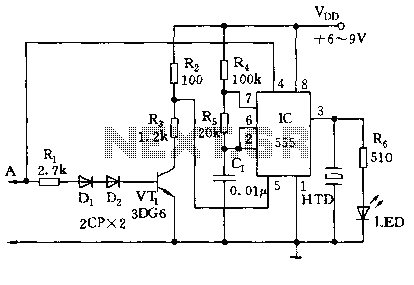
The circuit utilizes a 555 timer along with resistors R4, R5, and capacitor C1 configured in a controllable multivibrator mode. This setup forces the reset terminal (pin 4) to a specific state, allowing for control of the external logic...
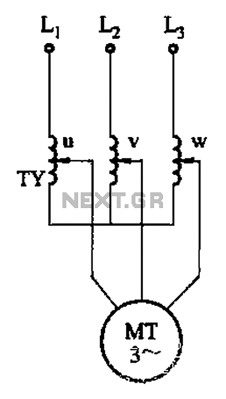
The circuit depicted in Figure 3-176 illustrates an adjustment method that allows the motor to operate at equilibrium. The adjustment range is relatively wide; however, it necessitates a three-phase voltage regulator, which incurs higher input costs. The circuit design in...
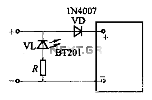
The adjustment potentiometer RP allows for modification of the over-voltage limit setting. In the event of reversed polarity in the DC power supply, there is a risk of damaging equipment components. To mitigate this risk, a reverse polarity protection...
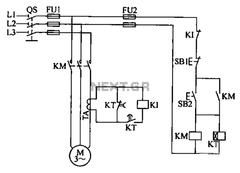
A three-phase electric motor overcurrent protection circuit. This example circuit utilizes a transformer to monitor the current, ensuring that the currents in the three-phase motor do not exceed normal operating levels. When the current exceeds the set threshold, the...
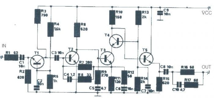
The T1 transistor must be of the BF200 type (or a similar variant), while the other transistors can be of the BF214 type. To achieve high efficiency, the antenna amplifier should be positioned at a short distance from the...
This receiver is designed around the widely used ZN414 integrated circuit (IC) and operates within the AM band, covering frequencies from 550 to 1600 KHz. To utilize the receiver for Longwave frequencies, it is necessary to replace the coil...
Warning: include(partials/cookie-banner.php): Failed to open stream: Permission denied in /var/www/html/nextgr/view-circuit.php on line 713
Warning: include(): Failed opening 'partials/cookie-banner.php' for inclusion (include_path='.:/usr/share/php') in /var/www/html/nextgr/view-circuit.php on line 713