
MSF Radio Time Clock
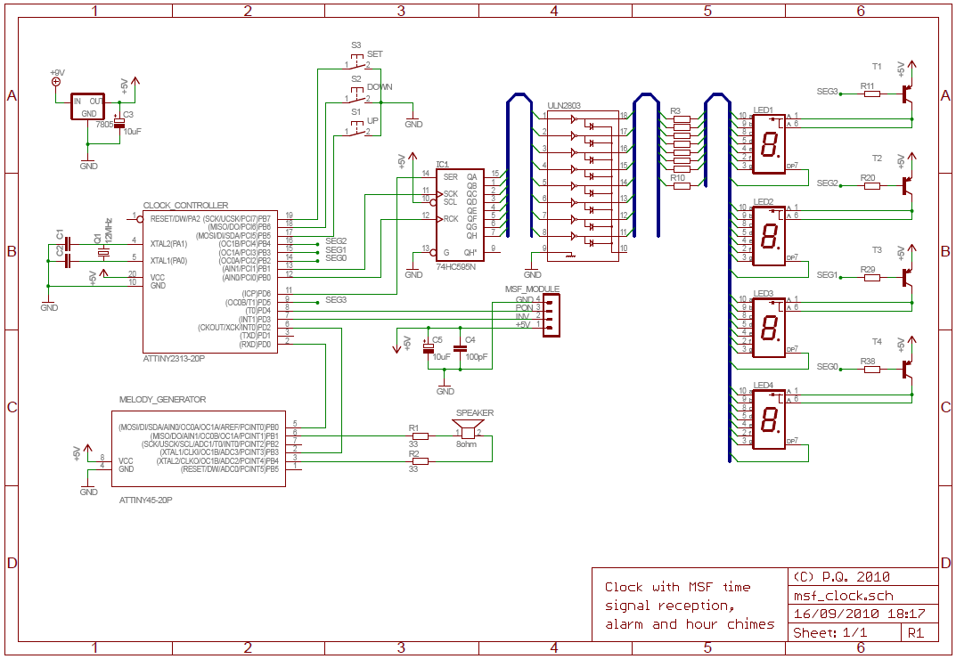
The display is multiplexed with simple transistor switches for the common anode. Only the middle two 7 segment displays have dots. I connected the anode transistors to the AVR with 2k2 resistors to limit current and the cathodes to a 74HC595 shift register via a ULN2803 Darlington array. I removed the controller IC and all other unused parts.
The AVR uses a 12MHz crystal which is accurate enough for keeping time. In my initial tests on the bench it varied by less than one second per day, but when installed in the clock case it loses about 3-4 seconds over 24 hours. Since the time is re-synchronized with the MSF signal every night that is more than adequate.
An MSF receiver module is connected to the AVR. I bought it for a few pounds and it works very well, although like most low frequency time code receivers it is extremely sensitive to noise. The multiplexed display has to be turned off while it is in use, so it is not possible to see the current time when it is being re-synchronized. I had to use a long USB cable for programming during development because the electrical noise from my PC was interfering. For details of the data format the Wikipedia page has some information about the signal which is mostly correct. The NPL documentation is also quite useful.
MSF reception requires fault tolerant code. Even under ideal conditions the signal is likely to contain noise. The decoded signal also has to be validated before being accepted.
The MSF reception routine waits for a pulse to start and then measures the length using a 100Hz timer. It rejects pulses (or drop-outs) of less than 5ms as noise. There is ±20ms leeway when decoding pulse lengths.
Once one complete minute's worth of pulses have been received they are decoded, sanity checked and parity checked. If the signal looks valid then the decoded data is stored and a second signal is received. If that second signal also passes all checks and gives a time exactly one minute after the first then it is deemed correct and the clock synchronised.
Synchronisation takes place when the clock is first powered on and again at 3AM every night. 3AM was chosen to avoid inconveniencing the user and because there is less RF interference at night.
A note about MSF signal accuracy. The broadcast time is supposed to be within 1ms of UTC. However, there is propagation delay between the transmitter and the receiver which cannot easily be measured or removed automatically. Based on where I live I estimate the delay to be around 275ms. GPS time compensates for this delay.
The project involves the integration of a digital clock with an MSF time signal receiver using an ATtiny2313 microcontroller. The microcontroller is tasked with receiving, decoding, and validating the MSF signal to ensure accurate timekeeping. The architecture includes a multiplexed display controlled by a 74HC595 shift register and a ULN2803 Darlington array for driving the common anode configuration of the 7-segment LEDs. The use of a 12MHz crystal oscillator provides a stable time base, while the incorporation of fault-tolerant code ensures reliability in the presence of noise.
The MSF reception algorithm is designed to capture and decode time signals with precision. It implements a timing mechanism using a 100Hz timer to measure pulse lengths, rejecting any pulses shorter than 5ms to filter out noise. The system requires two consecutive valid signals to confirm the accuracy of the received time data before synchronization occurs. This method enhances the robustness of the timekeeping system against potential signal degradation.
Additionally, the synchronization process is strategically scheduled for 3AM to minimize user disruption and interference from radio frequency noise. The estimated propagation delay of 275ms is acknowledged, and the system is designed to accommodate this delay for accurate time representation. Overall, the project exemplifies an effective application of microcontroller technology in timekeeping devices, leveraging both hardware and software solutions to achieve a reliable and user-friendly digital clock.The National Physics Laboratory broadcasts a time signal, previously known as the Rugby clock but now called "Time from NPL." Its most commonly known as the MSF signal due to it originally being identified in Morse code those letters. It is broadcast from Anthorn on 60kHz. Many commercial clocks use it to automatically set themselves. I decided to convert a digital clock I bought into one set by the MSF signal. To make the project more interesting I decided to use the ATtiny2313 microcontroller with only 2k flash ROM and 128 bytes of RAM.
Features: Automatically set by MSF time signal. Bright, flicker free display. Alarm with choice of 5 polyphonic melodies. Hour chime with choice of melodies and no chime between 00:00 and 08:00 The original clock electronics used two PCBs, one for the 7 segment LEDs and another for the clock controller and support hardware. I started by tracing the connections between them and mapping out how the display worked. The display is multiplexed with simple transistor switches for the common anode. Only the middle two 7 segment displays have dots. I connected the anode transistors to the AVR with 2k2 resistors to limit current and the cathodes to a 74HC595 shift register via a ULN2803 Darlington array.
I removed the controller IC and all other unused parts. The AVR uses a 12MHz crystal which is accurate enough for keeping time. In my initial tests on the bench it varied by less than one second per day, but when installed in the clock case it looses about 3-4 seconds over 24 hours. Since the time is re-synchronised with the MSF signal every night that is more than adequate. An MSF receiver module is connected to the AVR. I bought it for a few pounds and it works very well, although like most low frequency time code receivers it is extremely sensitive to noise.
The multiplexed display has to be turned off while it is in use, so it is not possible to see the current time when it is being re-synchronised. I had to use a long USB cable for programming during development because the electrical noise from my PC was interfering.
For details of the data format the Wikipedia page has some information about the signal which is mostly correct. The NPL documentation is also quite useful. MSF reception requires fault tolerant code. Even under ideal conditions the signal is likely to contain noise. The decoded signal also has to be validated before being accepted. The MSF reception routine waits for a pulse to start and then measures the length using a 100Hz timer.
It rejects pulses (or drop-outs) of less than 5ms as noise. There is ±20ms leeway when decoding pulse lengths. Once one complete minute's worth of pluses have been received they are decoded, sanity checked and parity checked. If the signal looks valid then the decoded data is stored and a second signal is received. If that second signal also passes all checks and gives a time exactly one minute after the first then it is deemed correct and the clock synchronised.
Synchronisation takes place when the clock is first powered on and again at 3AM every night. 3AM was chosen to avoid inconveniencing the user and because there is less RF interference at night. A note about MSF signal accuracy. The broadcast time is supposed to be within 1ms of UTC. However, there is propogation delay between the transmitter and the receiver which cannot easily be measured or removed automatically. Based on where I live I estimate the delay to be around 275ms. GPS time compensates for this delay. 🔗 External reference
Related Circuits
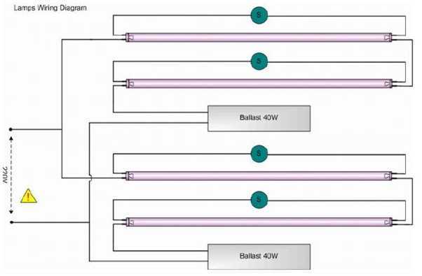
Four blacklight lamps, 15W each, emit radiation in the UVA region, with a peak around 350nm where the thin surface above the copper of the photosensitive board is sensitive. The lamps are taken by two and are connected in...
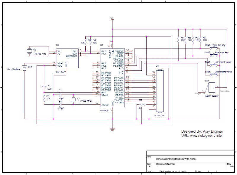
After the SCL line is high, the SDA line must be held low to indicate that the data being transmitted is legally binding. The data can only change when the SCL line is low. During the transfer of a...
This is the circuit diagram of a touch-activated alarm system that remains operational during power outages. The alarm system is triggered when someone touches the designated touch plate. A notable feature of this circuit is the automatic battery activator,...

This time delay switch circuit is designed to activate an AC load, such as lamps, after a delay of three minutes. It helps protect the load from inrush currents and transients during power-on, which can potentially harm the device....
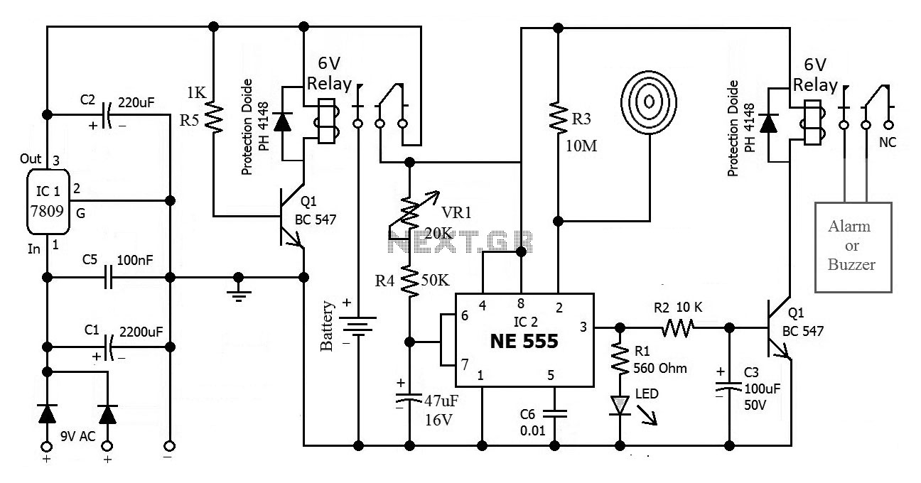
A very regular configuration of the 555 astable timer to work as a timer to trigger an alarm or any other equipment connected to pin 3. R resistor should be replaced with a potentiometer that will change the time...
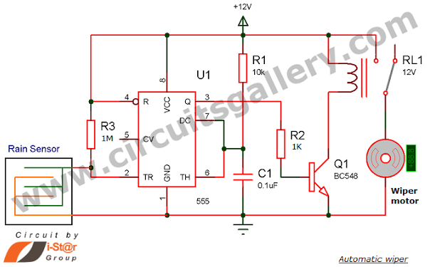
Have you seen Audi, Lexus, or Ford rain-sensing wipers and wondered how they operate in these vehicles? They are controlled by sensors located at the center of the windscreen, which detect raindrops and activate the wiper motor. The functioning...
Warning: include(partials/cookie-banner.php): Failed to open stream: Permission denied in /var/www/html/nextgr/view-circuit.php on line 713
Warning: include(): Failed opening 'partials/cookie-banner.php' for inclusion (include_path='.:/usr/share/php') in /var/www/html/nextgr/view-circuit.php on line 713