
FM radio with TDA7000
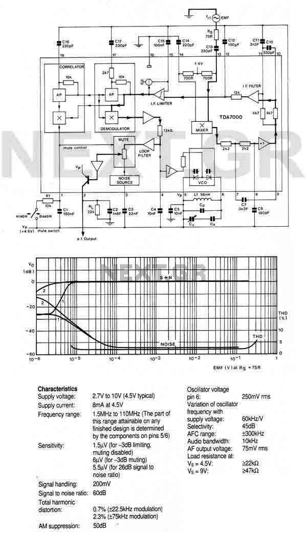
The FM radio chip described is a compact solution for FM radio applications, integrating multiple functions into a single device, which reduces the need for additional components and simplifies the design. The RF input stage is responsible for receiving the radio frequency signals, which are then processed by the mixer and local oscillator to downconvert the signal to an intermediate frequency (IF). The IF amplifier/limiter enhances the signal strength while maintaining a consistent output level, which is essential for clear audio reproduction.
The phase demodulator extracts the audio signal from the modulated carrier wave, converting it into a format suitable for audio output. The inclusion of a mute detector and mute switch allows for control over audio output, enabling the user to silence the output when needed, which is particularly useful in portable applications to conserve battery life and reduce noise.
The output stage is designed to directly drive a crystal earpiece, making it suitable for personal listening applications. Alternatively, when connected to a TBA820M amplifier, the system can deliver higher audio output levels, making it suitable for broader applications, such as portable radios that require louder sound output.
The accompanying graph provides valuable insights into the performance characteristics of the chip, illustrating how the audio output voltage and total harmonic distortion vary with changes in the input voltage and source impedance. This information is critical for engineers in evaluating the performance of the radio under different operating conditions, helping to optimize the design for specific applications. The ability to enable or disable the muting system also gives designers flexibility in terms of functionality and user experience. Overall, this integrated FM radio solution represents an efficient and effective choice for developing portable radio devices.An FM radio on a single chip requiring only a few simple peripheral components. In particular the ship requires only one simple coil and alignment is very easy. The chip includes an RF input stage, mixer, local oscillator, IF amplifier/limiter, phase demodulator, mute detector and mute switch. The output will directly drive a crystal earpiece or could be used with a TBA820M to form a complete portable radio.
Graph shows AF output voltage(Vo) and total harmonic distortion (THD) as a function of the emf input voltage (EMF) with a source impedance (Rs) of 75ohm : (1) muting system enabled; (2) muting system disabled. Note that the muting system can be disabled b 🔗 External reference
Related Circuits
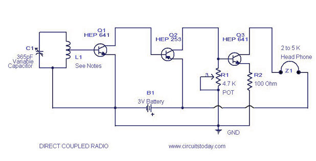
A simple direct-coupled radio circuit diagram and schematic, ideal for adjacent stations. This circuit uses Q1 as an audio amplifier, and the base-emitter capacitance provides radio filtering. The described circuit is a direct-coupled radio receiver designed to effectively operate with...
This compact device serves as a replacement for the input transistors and related circuitry on a single TO-220 style package. A decision was made to substitute the original driver board with a newly fabricated printed circuit board (PCB) designed...
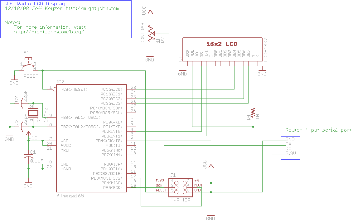
This is the seventh part of an ongoing series about building a low-cost, open-source streaming internet radio. If you have not already, check out the previous parts for some background about the project. In part six, UNIX-style shell commands...
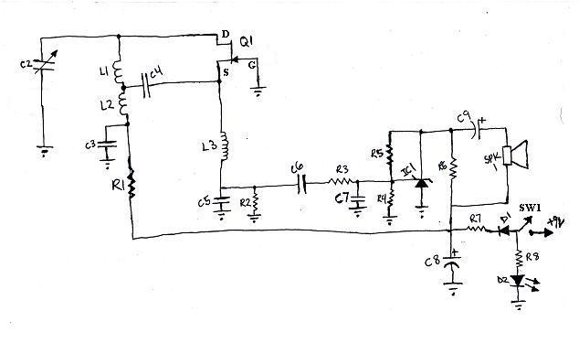
L1 and L2 were constructed by wrapping three tight loops side by side around a Sharpie marker. L2 was additionally created by wrapping approximately 8 inches of 35 AWG magnet wire around a ferrite core, ensuring that the windings...

This circuit is designed for an RF (radio frequency) transmitter experiment, where a watt meter is instrumental in optimizing the transmitter circuit. A simple RF watt meter circuit is illustrated in the schematic diagram below. The circuit is not...
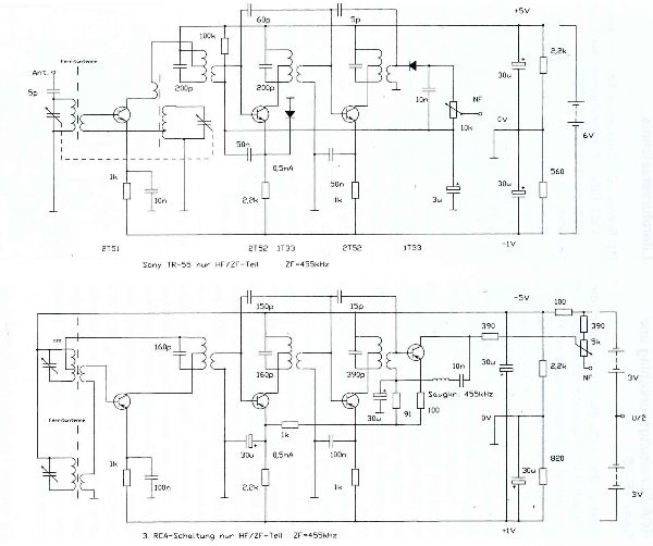
The TR-55 was the first transistor radio manufactured and sold in Japan. It utilizes the following transistors: 2T51 (oscillator-mixer), two 2T52 (for intermediate frequency), 2T53 (audio frequency driver), and 2T12. The first commercially available transistor radio was the Regency...