
The EC10 communications receiver
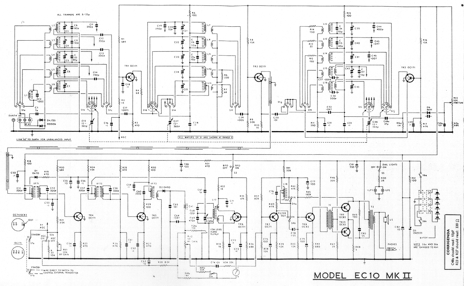
A drawback of the EC10 is its lack of an internal mains power supply; however, there is adequate space to add one. Current consumption with the lamps on is approximately 200 to 250 mA at 9 Volts, and voltage regulation is recommended since the internal zener regulator is sensitive to input variations. A small toroidal mains transformer is recommended over conventional I-E type transformers, which are bulkier and may introduce electromagnetic interference causing hum. To accommodate a transformer and power supply circuit within the EC10, a replacement panel for the battery compartment is necessary. It is important to note that the EC10 is Positive Earth, which can create issues if Negative Earth devices are connected to the same power supply, as contact between separate Earths can result in a short circuit across the common supply. It is advisable to use isolated (non-earthed output) power supplies, allowing a common ground or "0 Volt point" to be shared without complications.
After experiencing a lack of RF amplification in the EC10, an experimental modification was attempted as a temporary solution for the non-functional OC171. The EC10 employs a unique common base configuration for the first RF amplifier, likely to optimize the limited Hfe characteristic of the OC171. However, sensitivity decreases at higher frequencies. For those who wish to enhance performance for shortwave listening (SWL-DX) without concern for originality, replacing TR1 (OC171) with a modern Silicon PNP RF transistor can provide improvements at higher frequencies. Using a Silicon transistor instead of a Germanium one yields an immediate enhancement in signal-to-noise ratio. It is crucial to address bias and other DC conditions, as Germanium and Silicon transistors, while functioning similarly in terms of current amplification, have different DC characteristics. Resistor values must be adjusted to accommodate the replacement Silicon device. For this modification, a "2N2907" PNP Silicon transistor was utilized, as it was readily available. An equivalent part, "PN2907," can also be sourced from suppliers. After completing the modification and testing, an improvement in sensitivity at higher frequencies should be evident. Further gain can be achieved by reducing R3 to 150 Ohms, although this may lead to AGC overload at lower frequencies. A balance must be struck, as increasing RF gain can also heighten the risk of imaging problems above 20 MHz.One thing we should keep in mind is that the EC10 is now a vintage receiver, it has collector appeal. Any-thing we do should really be carried out in a manner that preserves the original state, most of the following adheres to this.
Things like replacing all of the Germanium transistors with Silicon devices could be done but this would be considered a radical modification. I have however, carried out some tests using a Silicon RF transistor as a replacement for the original Germanium transistor in the 1st RF amplifier. More on this later. The first and most basic thing you should do is replace all of the electrolytic capacitors, as many older types of electro`s are notorious for leakage.
Make sure you observe operating voltage and polarity. The BFO circuit was only intended for use with CW and even here a strong signal can cause problems, there`s just not enough coupling. To fix this problem and make SSB reception possible, you need to change C-67 on the IF / AF board from 1pF to 10pF, preferably polystyrene.
The result will be a greater level of BFO carrier coupling into the IF. You will need to use the BFO and tuning controls together as to much BFO carrier will swamp weaker signals, (keep AGC on) the fine tune on the later Mk-2 becomes quite useful here. A distinct disadvantage of the EC10 is the lack of an internal mains power supply, there is enough space to add your own but a few points need to be made.
Current consumption with the lamps on is around 200 to 250 mA maximum at 9 Volts and regulation of this voltage is recommended as the internal zener regulator is slightly sensitive to input variations. I recommend the use of a small toroidal mains transformer, conventional I-E type transformers are larger and suffer EM field leakage that may cause "Hum" problems.
To mount a transformer and supply circuit within the EC10, you need to make a replacement panel for the battery compartment. A point to note is that the EC10 is Positive Earth, this is not really a problem unless you try to run other Negative Earth devices off the same power supply, if the separate Earths come in contact, one has a short across the common supply.
It`s best to run separate Isolated (non-eathed output) power supplies, you can then share a common ground or "0 Volt point" without any problems. After finding my EC10 without RF amplification I tried an experimental mod as a temporary replacement for the dead OC171.
If you look at a circuit diagram of the EC10, you will find that it employs a rather unique common Base configuration for the first RF Amp. My guess is that this was done in order to make best use of the OC171`s somewhat limited Hfe characteristic, in any case sensitivity still falls off at higher frequencies.
If you intend to do some SWL-DX and don`t care about maintaining originality, you can pep things up a little on the higher frequencies by replacing TR1 (OC171) with a later Silicon PNP RF transistor. In using a Silicon transistor over a Germanium device there will be a instant improvement in signal to noise but we just can`t pull out the old and stick in the new.
We need to consider Bias and other DC conditions, a Germanium transistor does of course function in the same manner as a silicon device in that it amplifies current but the DC conditions are a little different. We need to rework the resistor values to suite our replacement silicon device. In this case I used a "2N2907" PNP Si device, simply because I had about a dozen of them in my collection.
You can get an equivalent "PN2907" from Dick Smith Electronics here in On completion and testing you should notice an immediate improvement in sensitivity at higher frequencies. You can further increase gain be reducing R3 to 150 Ohms but this will more than likely result in AGC overload at lower frequencies.
There is a trade off here, with increased RF gain you also increase the likelihood of imaging problems above 20 MHz. 🔗 External reference
Related Circuits
The OPA111 optical receiver amplifier features a feedback resistor of 200 MΩ, which is crucial due to the high gain of the amplifier. The OPA111 is designed to receive signals transmitted over optical fiber, specifically at a rate of...

Prior to the development of broadband communication receivers featuring synthesized oscillators, high-grade ham band receivers utilized crystal oscillators and a variable intermediate frequency (IF) to cover relatively narrow frequency segments of 500-600 kHz. The schematic illustrates a circuit designed...
This converter allows reception of six metre signals on a two metre receiver. It should therefore be useful for those with single or dual band sets that do not cover 50 MHz. More: To eliminate the need to obtain...
It is a high-quality FM receiver circuit based on the IC CXA1019. The CXA1019 is a monolithic silicon bipolar radio FM/AM receiver IC designed for Sony. The built-in circuitry within the CXA1019 includes an RF amplifier, mixer, oscillator, amplifier,...
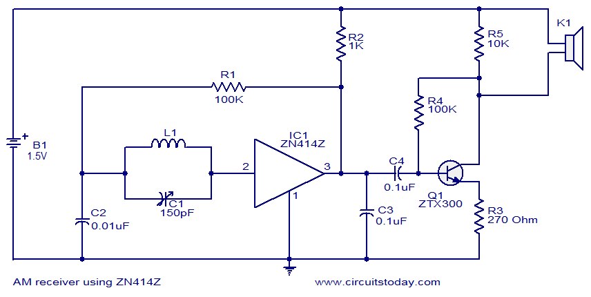
This circuit diagram represents a simple single-chip AM radio, designed around the ZN414Z integrated circuit (IC), which is a ten-transistor tuned radio frequency receiver. The IC features three leads and is housed in a TO92 package. It incorporates all...
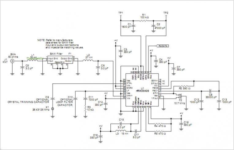
The RFRXD0420 and RFRXD0920 are low-cost, compact, single-frequency short-range radio receivers that require only a minimal number of external components for a complete receiver system. The RFRXD0420 operates within the frequency range of 300 MHz to 450 MHz, while...