
FM SCHEMATICS

The FM amplifier serves as a critical component in the transmission chain of a broadcast radio station, enhancing the quality and reach of the audio signals. The solid-state design not only provides robustness but also ensures higher efficiency and reliability compared to traditional vacuum tube amplifiers. The specified gain of 9 dB is sufficient for many applications, but the amplifier's capability to output up to 100 watts allows for extensive coverage, making it suitable for both personal and commercial broadcasting needs.
The BA1404 Hi-Fi Stereo transmitter is particularly noteworthy for its versatility and ease of use. Its ability to interface with multiple audio sources broadens its applicability, catering to a variety of user needs, from casual music streaming to more sophisticated broadcasting setups. The meticulous design process, which involved testing various configurations, underscores the importance of optimizing circuit elements to achieve superior performance.
The choice of a 3.5-turn variable coil is especially significant, as it directly impacts the frequency stability of the transmitter. This stability is paramount in professional broadcasting, where even minor fluctuations can lead to significant audio quality degradation. The use of a 38 kHz crystal oscillator serves to anchor the frequency, ensuring that the stereo encoding remains consistent and reliable.
The implementation of decoupling capacitors is a critical design consideration. By placing these capacitors as close as possible to the BA1404 chip and the variable coil, the circuit minimizes the potential for noise interference, which is vital for maintaining audio fidelity. The ground plane on the PCB further enhances performance by reducing electromagnetic interference and providing a stable reference point for the circuit's operation.
The compact design of the amplifier, housed in an aluminum die-cast box, not only protects the components but also aids in thermal management, which is essential for maintaining performance over extended periods. The use of coaxial sockets for RF connections ensures minimal signal loss, an important factor in maintaining the integrity of the transmitted signal.
In summary, this FM amplifier and transmitter design represents a well-thought-out approach to achieving high-quality audio transmission, combining advanced engineering principles with practical usability. The careful selection of materials and components, along with a focus on circuit layout and design, ensures that users can achieve optimal performance in their broadcasting endeavors.FM amplifier is used for amplify signal from exciter in broadcast radio station. In this page, RF FM Amplifier uses solid state material with minimum gain 9dB. Input of the FM Amplifier needs 5-10 watt with power output about 100 watt. Whether you want to create your own radio station, transmit the music around the house, or simply create a wirele ss link between your iPod and a receiver in your car, this transmitter will let you do these things easily. With BA1404 HI-FI Stereo transmitter you will be able to transmit MP3 music from your iPod, computer, discman, walkman, TV / SAT receiver, and many other audio sources.
The above FM transmitter design is a result of many hours of testing and tweaking. The goal was simple; to test many existing BA1404 transmitter designs, compare their performance, identify weaknesses and come up with a new BA1404 transmitter design that improves sound quality, has very good frequency stability, maximizes transmitter`s range, and is fairly simple for everyone to build. We are happy to announce that this goal and expectations have been met and even exceeded. The transmitter can work from a single 1. 5V cell battery and provide excellent crystal clear stereo sound. It can also be supplied from two 1. 5V battery cells to provide the maximum range. One of the qualities of BA1404 FM transmitter is excellent frequency stability. This is mainly due to a use of high quality 3. 5 turn variable coil. Tunable RF coils are ideal for precise frequency tuning because their magnet wire is halfway embedded within the plastic, which minimizes frequency drifts.
Regular air coils are not preferred for professional broadcasting because the coil expands and contracts with temperature changes. That`s the very reason why variable coil was chosen as a substitution for an air coil and a variable capacitor.
Another quality of the presented BA1404 transmitter is a crystal clear stereo sound and improved sound separation. There are several factors that account for improved sound quality and a separation. First reason is the use of 38 KHz crystal which provides rock solid frequency for stereo encoder. Another reason is the use of two 1nF decoupling capacitors one for BA1404 chip and another for 3. 5 variable coil. These capacitors have to be as close as possible to a BA1404 chip and a variable coil because this will GREATLY improve the sound quality, sound separation and even frequency stability as well.
What they do is filter out the noise in the incoming DC voltage. If the noise enters BA1404 chip stereo generator will include it in a transmitted sound affecting both the sound and multiplex signal that is responsible for generation of the clear stereo signal. If that noise enters it will also be included in a generation of subcarrier frequency affecting the frequency stability.
Most people are not aware of how important this is and might place them in a wrong location, away from the target components which provides no use, or worse decide not to use these capacitors at all. Another factor that is extremely important and which improves overall quality of the whole BA1404 transmitter including frequency stability, sound quality and sound separation is the use of the ground plane on the transmitter`s PCB.
It is recommended that ground plane should always be used in circuits that deal with higher frequencies. This a suggested high-resolution PCB layout for BA1404 Transmitter. It is ready for printing and no further adjustments are necessary. Dimensions of the PCB should be 57 mm x 35 mm (W x H). This a suggested high-resolution PCB layout for BA1404 Transmitter. It is ready for printing and no further adjustments are necessary. Dimensions of the PCB should be 57 mm x 35 mm (W x H). ConstructionThe amplifier was constructed in a small aluminium diecast box. RF input and output connections are made by coaxial sockets. The power supply is routed through a ceramic fee 🔗 External reference
Related Circuits
This chapter provides detailed schematics of various power supplies suitable for use with common Ar/Kr ion tubes available to hobbyists in the surplus market. Included are examples of commercial designs (Omnichrome 150R and 532 head, Lexel 88 and head)...
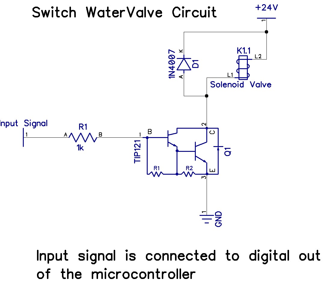
The Arduino Uno has adequate memory and ports, but efficient programming is necessary to store settings in memory. The Mega version offers increased memory and ports. The Shako valve operates on 24 volts DC; however, 12 volts is preferred...
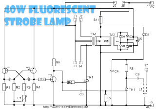
This circuit is designed for a 40 Watt fluorescent lamp. It operates similarly to a traditional strobe light, but utilizes a fluorescent tube instead. The fluorescent tube remains continuously energized, with both electrodes supplied with electricity. This current causes...
This index is organized alphabetically by each word, excluding prepositions. For instance, the "Frost Alarm" will be listed under both "A" and "F." To efficiently locate a circuit, utilize the top index or employ your browser's search function. In...
Here they exist two regulator circuits, that use the IC L200, as regulator of voltage and current, the company SGS-Thomson, which give these circuits. In circuit Fig.1, we can regulate the output voltage, with the RV1, while in the...
The schematics on this page are provided strictly for educational purposes. If anyone intends to use these designs for profit, they are required by law to obtain permission from the legal owner(s) of the design and comply with any...