
FM Stereo Transmitter circuit diagram Using BH1417

The FM transmitter circuit utilizing the BH1417 is designed for efficient and reliable audio transmission in the FM broadcast band. The integrated circuit BH1417 serves as the heart of the transmitter, providing a range of essential features that facilitate high-quality audio broadcasting. The pre-emphasis circuit enhances higher frequency audio signals, ensuring that the transmitted sound is clearer and more dynamic. The limiter function is crucial for preventing distortion during transmission, particularly when dealing with varying audio levels, thus maintaining a consistent output.
The stereo encoder allows the circuit to transmit stereo audio signals, enhancing the listening experience for users. The low-pass filter is an essential component that helps to eliminate unwanted high-frequency noise, which can cause interference with the RF signal. This feature is particularly important in maintaining the integrity of the transmission, especially in environments with multiple radio frequency sources.
The PLL circuit is a sophisticated feature that locks the transmission frequency to a stable value, preventing drift that can occur due to temperature changes or component variations. This stability is critical for ensuring that the signal remains on the intended frequency, thereby minimizing interference with other broadcasts.
The FM oscillator and RF output buffer work together to generate and amplify the RF signal, ensuring that it is strong enough for transmission over the desired range. The inclusion of a 4-DIP switch allows users to easily select from 14 different transmission frequencies, enhancing the flexibility of the device. This feature is particularly useful in urban areas where multiple FM stations may be operating simultaneously, allowing the user to find an unused frequency.
The power requirements of the BH1417 are modest, with a voltage range of 4 to 6 volts and a low current consumption of around 30 mA. This makes the circuit suitable for battery-operated applications, providing a practical solution for portable FM transmission needs. The RF power output of 20 mW is adequate for short-range broadcasting, making it ideal for personal use or small events.
Overall, the BH1417 FM transmitter circuit is a versatile and efficient solution for audio transmission, combining multiple functionalities in a compact package while ensuring high-quality performance and ease of use.This circuit is a circuit diagram is included in the RF circuit. FM Transmitter circuit diagram using the IC BH1417. Where the integrated circuit design from RHOM which includes many features in one small package. He came with pre-emphasis, limiter so that music can be transmitted in the same audio level, stereo encoder for stereo transmission, lo w pass filter that blocks audio signals above 15KHz to prevent RF interference, PLL circuit that provides a solid frequency transmission (no more frequency drift), FM oscillator and RF output buffer. The following is a schematic drawing: There are 14 possible transmission frequencies with 200KHz adding that the user can choose a 4-DIP switch.
Band lower frequency ranging from 88. 7 to 89. 9 MHz, and the frequency band from 107. 7 to 108. 9 MHz. BH1417 can be given with 4-6 voltage and consumes only around 30mA, provides RF power output of 20mW. BH1417 provides 40db channel separation is quite good, although older BA1404 FM Transmitter chip provides 45dB channel separation a little better.
🔗 External reference
Related Circuits
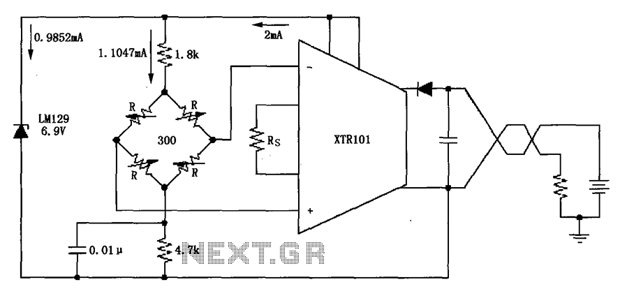
The circuit utilizes the LM129 voltage regulator to produce a 6.9V voltage reference, supplying a current of 1.0147mA from the 6.9V reference voltage to the bridge. The bridge may consist of varistor-type pressure sensors. The LM129 voltage regulator is a...
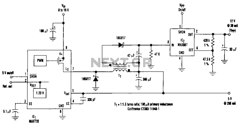
By adding a flyback winding to a buck-regulator switching converter, which functions as a 5-V supply with a 200-mA output capability, a 12-V output can be generated. The flyback winding on the main inductor, forming transformer T1, allows for...
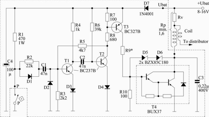
This scheme is designed for a four-cylinder engine. It aims to reduce fuel consumption, increase speed slightly, and minimize the need for frequent access to the distributor cap for contact button replacement, thereby saving costs. Transistors T1 and T2...
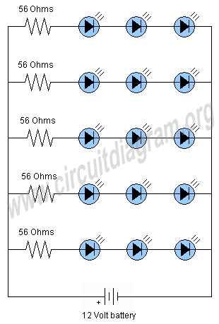
This project involves a 12V LED lamp circuit that is notably simple. The circuit comprises five resistors and fifteen super bright white 5mm LEDs, which are readily available at low prices. It is compatible with any type of 12-volt...
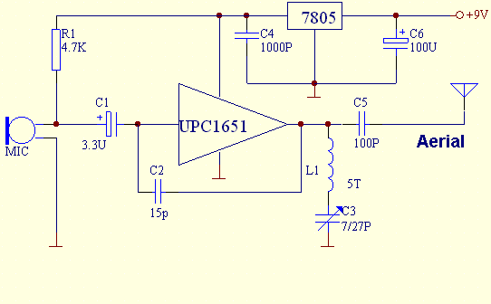
This FM transmitter is built with UPC1651, which is a silicon monolithic integrated circuit specifically designed as a wideband amplifier covering the HF band. The UPC1651 is a versatile integrated circuit that serves as a key component in FM transmitter...
This is a single-chip FM transmitter circuit utilizing the Maxim semiconductors IC MAX2606. The MAX2606 is a compact, high-performance intermediate frequency voltage-controlled oscillator (VCO) specifically designed for wireless communication applications. It features a monolithic construction that ensures low noise...
Warning: include(partials/cookie-banner.php): Failed to open stream: Permission denied in /var/www/html/nextgr/view-circuit.php on line 713
Warning: include(): Failed opening 'partials/cookie-banner.php' for inclusion (include_path='.:/usr/share/php') in /var/www/html/nextgr/view-circuit.php on line 713