
XTR101 bridge input voltage excitation circuit diagram
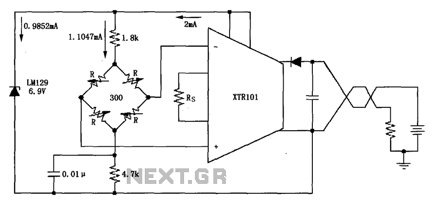
The LM129 voltage regulator is a precision device designed for generating stable reference voltages. In this circuit, it is configured to output a nominal voltage of 6.9V, which is crucial for ensuring accurate readings from the connected sensors. The output current of 1.0147mA is specifically chosen to meet the requirements of the bridge sensor without exceeding its operational limits, thereby ensuring reliable performance.
The bridge sensor in this application is likely a varistor-type pressure sensor, which utilizes the principle of resistance change under varying pressure conditions. These sensors are known for their sensitivity and fast response times, making them suitable for applications requiring precise pressure measurements. The bridge configuration allows for differential measurements, which enhances the accuracy of the readings by canceling out common-mode noise and other interferences.
Additionally, the circuit may include passive components such as resistors and capacitors to filter noise and stabilize the voltage output. Proper layout and grounding techniques should be employed to minimize electromagnetic interference (EMI), which can affect the performance of the voltage reference and the sensor readings.
In summary, the integration of the LM129 voltage regulator with a varistor-type bridge sensor in this circuit provides a robust solution for generating a stable voltage reference and accurate pressure measurements, essential for various applications in electronics and instrumentation. As shown, the circuit uses the LM129 regulator to generate 6.9V voltage reference, provided 1.0147mA current from 6.9V reference voltage to the bridge. Bridge may be as pressur e sensors varistor-type bridge sensor.
Related Circuits
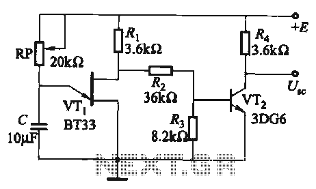
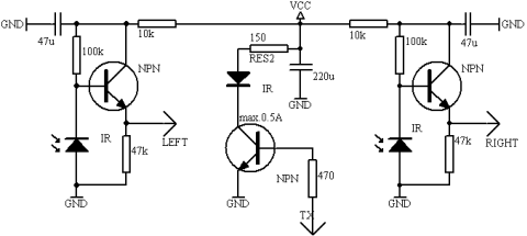
The circuit comprises a single-junction transistor VTi, a resistance Ri, a potentiometer RP, and a capacitor C, forming a relaxation oscillator and an amplifier transistor VTz. The adjustment potentiometer RP allows for changing the relaxation oscillation frequency, providing a...
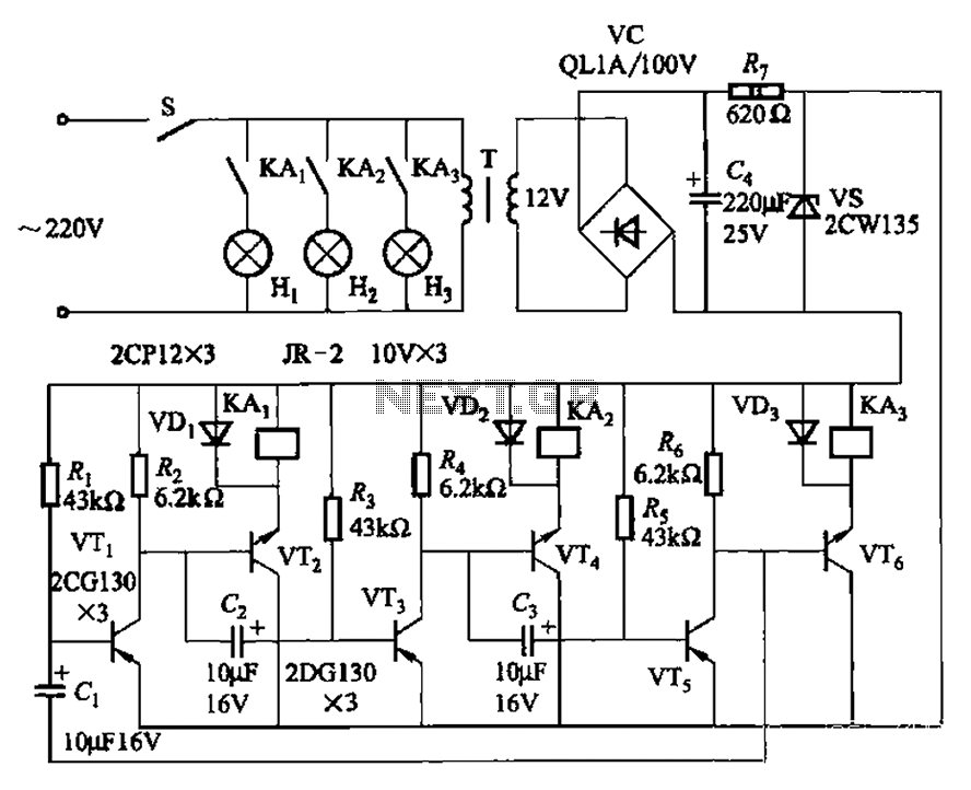
The transistors VTi, VT3, and VTs, along with the RC components, form three distinct multi-resonator oscillators. The oscillation frequency levels are dependent on the values of Ri, R3, Rs, and Cl, as well as Cz and C3s. The circuit comprises...
The current source in the diagram reacts very quickly to changes in the input signal and may be utilized in specific measurements. The differential amplifier IC1 ensures that the voltage across resistor R2 is equal to the input voltage,...
This circuit functions to monitor the duration of occupancy in a toilet, activating an alert if the time spent exceeds a predefined limit. The components involved include a resistor, integrated circuit (IC), capacitor, and transistor. The occupancy monitoring circuit is...
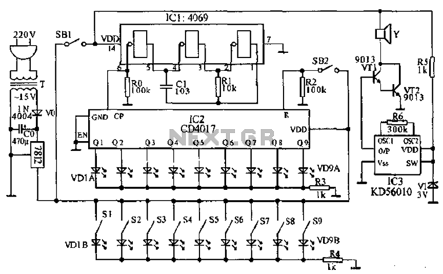
This document presents a principle circuit for electronic games. The main circuit operates in conjunction with the host through the reset button SB2, while the indicators VD1A-VD9A remain off. Prizes, for example, five, are determined by the number of...
This document presents a collection of engaging and challenging electronic circuits that can be built for enjoyment. The author has a long-standing passion for electronics, having studied the subject since middle school and developed numerous circuits over the years....