
electronic car ignition circuit
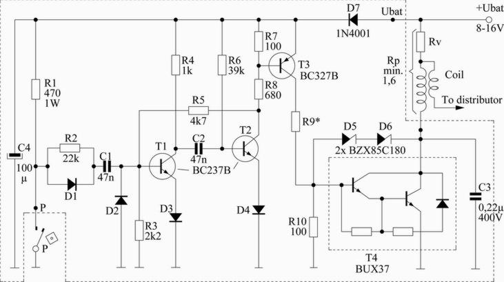
The electronic ignition schematic employs a monostable multivibrator configuration using T1 and T2 to generate controlled impulses for the ignition system. The timing of the ignition is critical for optimizing engine performance, and the values of C2 and R5 are chosen to achieve an impulse duration of 1.5 milliseconds, allowing for precise control of the ignition timing.
When switch P is engaged, T1 remains inactive, and T2 is activated, which allows for the conduction of current through T3 and T4, thereby energizing the primary coil. The design ensures that when the ignition switch is opened, T1 briefly activates, allowing C2 to charge through R6, which facilitates the timing mechanism that ultimately turns T2 off. This off state is crucial as it interrupts the current flow through T4, protecting the system from excessive current draw.
The inclusion of R2 and D1 serves to stabilize the circuit by preventing false triggering of the monostable multivibrator due to switch bounce. The Zener diodes Z5 and Z6 are strategically placed to clamp voltage spikes that may occur due to inductive kickback from the primary coil, thereby safeguarding the sensitive components in the ignition circuit.
The choice of a coil ratio of 1:80 or 1:100 is significant as it ensures that the ignition system operates efficiently while the external resistor Rv aids in thermal management. Maintaining a total resistance of at least 1.6 ohms is essential to limit the current through T4 to a safe level, preventing overheating and potential damage to the ignition system. This comprehensive design allows for enhanced engine performance while ensuring reliability and cost-effectiveness in operation.This scheme is for 4 cylinder motor. This will make your car spent less fuel, be a little bit faster and you wont have to frequently open your distributor cap to change the contact buttons thus wasting less money. T1/T2 create one monostable multivibrator in which C2 and R5 determine the length of impulse which is 1, 5 msec.
Next in line are T3 and then T4 which is Darlington transistor specially developed for electronic ignition which is used as a switch to turn on/off primary coil. Impulses from switch P turn on monostable multivibrator T1/T2. You need to un-connect capacitor that is in distributor cap because it is not needed anymore. While switch P is closed T1 is in off state but T2 is in on state, also T3 and T4 which enables current to flow trough primary coil.
When switch P is opened, T1 gets in on state for a moment causing C2 to charge over R6 which makes T2 go to off state because of voltage drop on R6. When T2 is off also T3 and T4 are off and current that was flowing trough primary coil is stopped. Because T2 is in off state, voltage on R8 is increased which is passed trough R5 on T1 base which is still in on state and C2 is still charging.
After 1, 5 msec. C2 value reaches the level where T2 goes to on state again and T1 goes to off state. Now T2, T3 and T4 are in on state, again, and current flows trough primary coil again. R2 and D1 are used to neutralize the effect of impulses caused from «jumping » of switch P which could turn on monostable multivibrator when it shouldn`t. Zener diodes Z5 and Z6 are together with R10 limit overcharged voltage impulses that are caused by self induction of primary coil which could damage T4.
They should be connected as close as possible to T4. Coil should have ratio of 1:80 or 1:100 with external resistor Rv which is used for better cooling. Total resisting value (Rp) of primary coil and Rv resistor shouldn`t be under 1, 6 ohm`s so current trough T4 wouldnt be bigger than 10A. 🔗 External reference
Related Circuits

The operation and circuit diagram of a low-cost amplifier utilizing BC107 and BC148 transistors are explained in detail. The low-cost amplifier circuit employs two types of transistors, BC107 and BC148, which are commonly used for their favorable characteristics in audio...
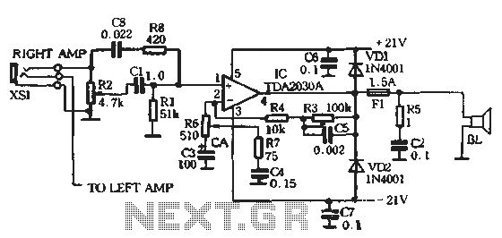
The circuit comprises two main components: the Lisheng power amplifier and the rectifier filter section. The stereo audio power amplifier circuit diagram, depicted in Figure 5-85, illustrates only one channel, with the other channel being identical. The audio signal...
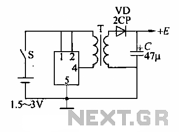
A DC booster circuit is illustrated in the figure, which represents a step-up transformer circuit diagram. The step-up transformer (T) can be utilized to power small transistor radios. The winding ratio can be adjusted to achieve the desired output...
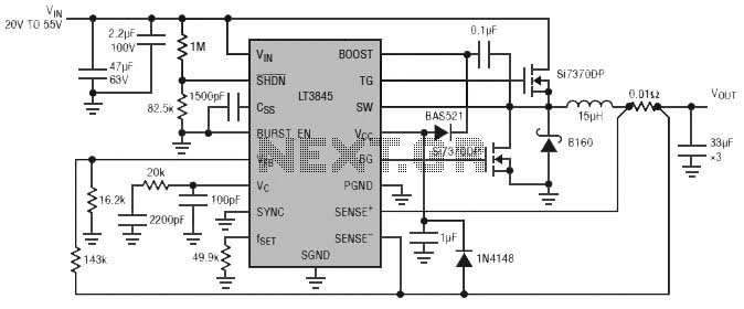
Burst Mode operation maintains high efficiency at light loads by reducing IC quiescent current to 120 µA. Light load efficiency is also improved with the reverse inductor current inhibit function, which supports discontinuous operation. Additional features include an adjustable...
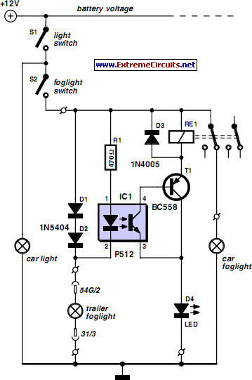
For several years, a rear fog lamp has been mandatory for trailers and caravans to enhance visibility in foggy conditions. When this fog lamp is activated, the fog lamp of the towing vehicle must be turned off to prevent...
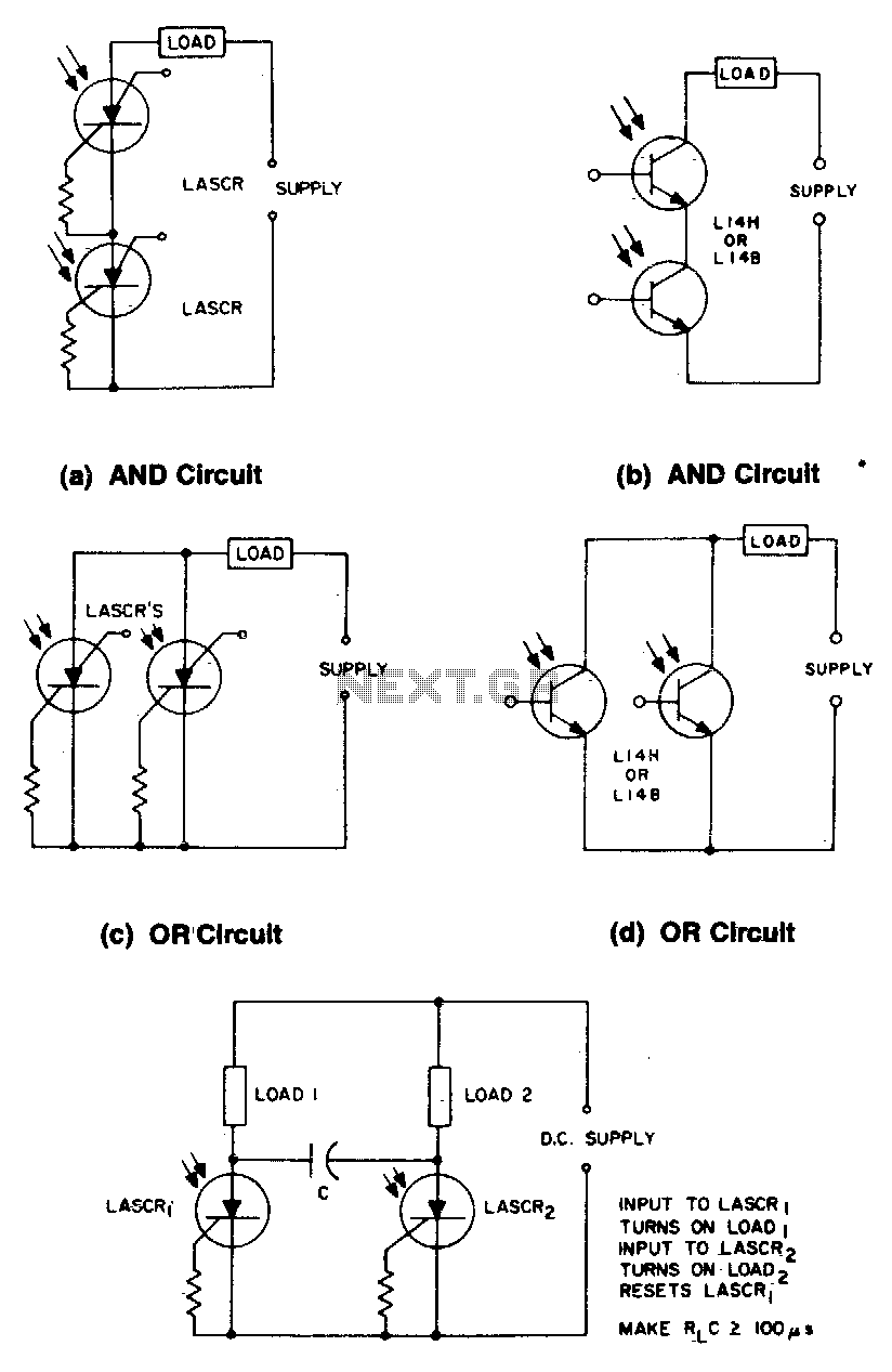
These circuits illustrate some of the common logic functions that can be implemented. The provided circuits serve as examples of fundamental logic functions utilized in digital electronics. Logic functions are the building blocks of digital systems, enabling the execution of...
Warning: include(partials/cookie-banner.php): Failed to open stream: Permission denied in /var/www/html/nextgr/view-circuit.php on line 713
Warning: include(): Failed opening 'partials/cookie-banner.php' for inclusion (include_path='.:/usr/share/php') in /var/www/html/nextgr/view-circuit.php on line 713