
FM Tracking Transmitter
When using longer leads that penetrate the backside of the perfboard, connections can be made by bending and soldering the leads as illustrated on the circuit board's underside. For powering the transmitter with two lithium batteries, a stiff steel wire (such as that from a metal paperclip) can be fashioned into a battery hold-down clip and negative terminal contact, as depicted. If using a 9-volt transistor radio battery, a 9-volt battery snap connector should be soldered to the perfboard instead of the battery hold-down clamp. The red wire from the battery connector connects to the hole marked "+", while the black wire connects to the hole marked "-". A 9-volt battery holder should be glued to the end of the circuit board to secure the battery.
The antenna should be connected as shown; it can be any wire of appropriate length, but a stiff wire made from a steel guitar string is particularly effective. The antenna length can range from 18" to 27", with 18" being the most reliable. The transmitter should be secured in a non-metallic vise or wooden block to prevent movement during tuning. Using a non-metallic alignment tool, the screw on capacitor C5 should be turned slowly without touching the circuit, while positioning the antenna to extend away from the side. A non-metallic alignment tool can be made by shaping the tip of a wooden or plastic screwdriver.
As C5 is adjusted, multiple signal spots will be detected, but only one will yield the loudest sound, indicating the correct frequency, comparable to commercial radio stations. The receiver should be slightly retuned to optimize reception of the exact signal. When the transmitter is properly adjusted, a loud and clear "beeping" sound will be audible, with volume decreasing when the radio is tuned away from the signal. The transmitter may become "detuned" by nearby objects or movements of battery wires and the battery itself. Therefore, it is advisable to place the transmitter in a small enclosure, securing the circuit board, battery holder, wires, and antenna to prevent any movement. Silicone rubber glue is suitable for this purpose, and a small hole can be created in the box for tuning capacitor C5. The enclosure does not need to be a standard project box; it can be any suitable container.
This design provides a straightforward approach to creating a functional tracking transmitter that can be used for various applications, ensuring reliable performance when properly assembled and tuned.The following plans describe how to build a very small tracking transmitter that can be tracked using an FM broadcast band radio receiver. The transmitter is powered by a 3 volt to 9 volt battery and has a range of from 1/4 mile to over 1 mile depending on battery voltage, T1.
ECG 6410 UJT. 526-NTE6410. not available The transmitter can be assemb led in a variety of configurations although good VHF circuit technique should be followed. The illustration included with these plans shows one of many possible layouts. It is one which has been tested and found to work well. The components are assembled on a small piece of perfboard of approximately 3/4" by 1 3/4". The leads are mounted through the holes as shown and soldered together on the back side of the perfboard. Some jumpers are made on the backside of the perfboard to connect the various components. Note that a Printed Circuit Board (PCB) pattern is also include should you wish to make a PCB. The asembly is the same for PCB construction except the jumpers used on the backside of the perfboard are not required since the foil pattern replaces them.
4. Using some of the longer leads that are penetrating through the backside of the perfboard make the connections as shown in the pictorial on the bottom side of the circuit board by bending the leads and soldering. 5. If the transmitter is to be powered by two(2) lithium batteries use a stiff steel wire (possibly obtained from a metal paperclip) to fashion the battery hold down clip and the negative terminal contact as shown in the pictorial.
6. If the transmitter is to be powered by a 9 volt transistor radio battery, solder a 9 volt battery snap connector to the perfboard instead of the battery hold down clamp described in step "6". Connect the red wire from the battery connector to the hole marked "+" and the black wire to the hole marked "-".
Glue a 9 volt battery holder to the end of the circuit board to hold the battery. 7. Connect the antenna as shown. The antenna can be any piece of wire of the appropriate length. However, a stiff wire made from a steel guitar string works exceptionally well. The antenna can be any length from 18" to 27", however an 18" antenna is probably the most dependable. 11. Secure the transmitter in a nonmetallic vise or brace in a wooden block. The idea is to secure the transmitter so that it will not move when it is tuned. 12. Using a nonmetallic alignment tool very very slowly turn the screw on C5. Do not touch the circuit and position the antenna so that it extends away to the side. (Note: a nonmetallic alignment tool is nothing more than a wooden or plastic screw driver with a very thin and flat tip.
One can be easily made by whittling a flat tip on a 6" to 10" stick or wooden dowel rod. ) 13. As C5 is turned there will be many spots where a signal will be heard. However, there will only be one spot that will be the loudest and represents the exact frequency. It will be as loud as most of the commercial radio stations and will be several orders of magnitude louder than any other spot. Tune C5 several times working slowly into the loudest signal. 14. Retune the receiver slightly to peak the reception to the exact signal. When the transmitter is properly tuned a loud and clear "beeping" should be heard and when the radio is tuned to either side of the signal the "beeping" should decrease in loudness.
This transmitter can be easily "detuned" by just about anything that comes near the circuit board or antenna. Tuning is also effected by the movement of battery wires and the battery. Therefore, it is recommended that the transmitter be placed in a small box and the circuit board, battery holder, battery wires, and antenna secured to the box so that nothing can move or slide about.
Silicon rubber glue works well for this purpose. A small hole can be made in the box for tuning C5. The box need not be a standard project box but can be just abo 🔗 External reference
Related Circuits
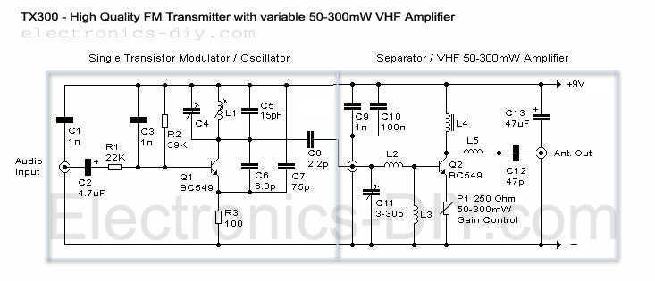
Here it is a brand new TX300 FM transmitter. The amplifier has exactly the same architecture as TX500 with the difference that TX300 has only one stage variable VHF amplifier. It is a cute schematic that was made for...
A highly effective 1-watt FM transmitter circuit that is easy to construct. The circuit consists of four transistors: one functions as a stable oscillator, followed by a buffer stage to maintain frequency stability during adjustments. Next is a resonance...
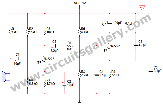
This is a simple 2N2222 transistor-based FM transmitter circuit that operates within the FCC (Federal Communications Commission) limits, meaning no license is required for its use. FM stands for Frequency Modulation, which is a method of transmitting radio frequency...
The circuit of an FM Tracking Transmitter Circuit or Remote Control Transmitter Circuit is explained using a 555 IC and 2N4392 transistors. The FM Tracking Transmitter Circuit utilizes a 555 timer integrated circuit (IC) configured in astable mode to generate...
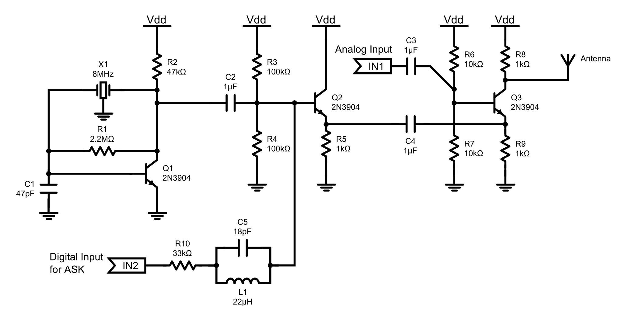
This is an 8MHz amplitude modulated (AM) radio transmitter designed primarily for practical applications and as an educational exercise in electronics. The objective was to create a simple radio transceiver that could be used in future projects requiring basic...
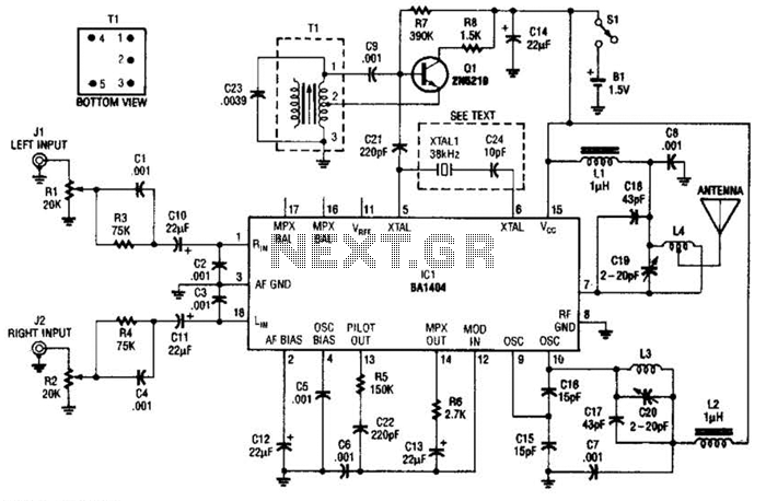
In this application, a BA1404 is utilized to generate an FM MPX baseband signal. This signal modulates a crystal oscillator (Q3) through a dual varactor series modulator. This transmitter can be used to play CD audio on an existing...