
FM Tracking Transmitter Circuit or Remote Control Transmitter Circuit
The FM Tracking Transmitter Circuit utilizes a 555 timer integrated circuit (IC) configured in astable mode to generate a frequency-modulated signal. This configuration allows the circuit to produce a continuous wave signal that can be modulated by varying the input voltage. The 555 timer is known for its reliability and versatility in timing applications and signal generation.
In this circuit, the 2N4392 transistors serve as amplifiers to boost the output signal from the 555 timer, ensuring that the transmitted signal has sufficient power to cover the desired range. The transistors are configured in a common emitter arrangement, providing both amplification and the ability to drive an antenna for effective transmission.
The circuit typically includes additional components such as resistors and capacitors, which are crucial for setting the frequency of modulation and controlling the bandwidth of the transmitted signal. The values of these components can be adjusted to tune the transmitter to the desired frequency range, making it suitable for various remote control applications.
An antenna is connected to the output stage of the circuit, allowing the FM signal to be transmitted over a distance. The design can be further enhanced by implementing filtering techniques to reduce unwanted harmonics and improve signal clarity.
This FM Tracking Transmitter Circuit can be employed in various applications, including remote control systems for toys, vehicles, and other electronic devices, showcasing the flexibility and effectiveness of the 555 timer and 2N4392 transistor combination in RF transmission scenarios.The circuit of a FM Tracking Transmitter Circuit or Remote Control Transmitter Circuit is explained using 555 IC and and 2N4392 transistors.. 🔗 External reference
Related Circuits
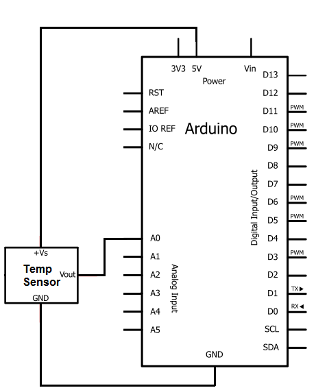
The integrated circuit (IC) used for temperature measurement is the TMP36. This IC will be integrated with an Arduino to obtain temperature readings. The Arduino will read the measured value from the TMP36 and convert it into degrees Fahrenheit,...
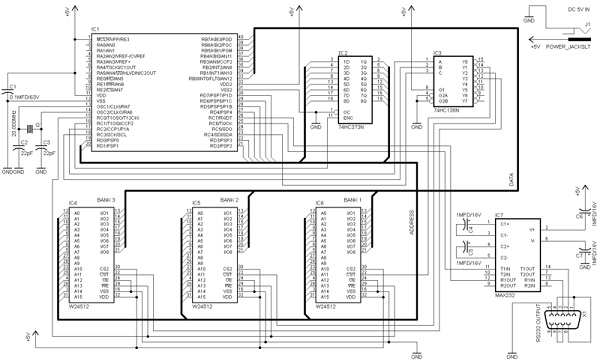
A RAM memory extender has been designed for PIC microcontrollers. This circuit incorporates various logic integrated circuits (ICs) and SRAM memory modules to enhance the data memory capacity of a PIC microcontroller. The designer has also supplied source code...
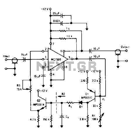
The amplifier drives the base of a common emitter PNP MPS6517, operating with a voltage gain of approximately 20. The RL control adjusts the quiescent point of transistor Q, allowing varying amounts of input signal to exceed the reference...
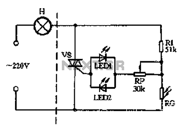
The circuit section includes a photoresistor (RG) and a fixed resistor (Rl) that form a voltage divider. Light-emitting diodes (LED1 and LED2) serve a dual purpose as power indicators and trigger rectifiers. During the positive half-cycle of the alternating...
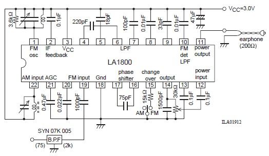
This portable AM/FM radio circuit is designed using the LA1800 integrated circuit (IC) along with several external components. The LA1800, manufactured by Sanyo Semiconductors, requires only a few additional components for its operation. The output signal is directed to...

This amplifier is designed with the following specifications: distortion less than 0.1% at full power of 100W even at 20KHz, with power attributed to an extended bandwidth. The output transistors are protected against short circuits, and the power supply...
Warning: include(partials/cookie-banner.php): Failed to open stream: Permission denied in /var/www/html/nextgr/view-circuit.php on line 713
Warning: include(): Failed opening 'partials/cookie-banner.php' for inclusion (include_path='.:/usr/share/php') in /var/www/html/nextgr/view-circuit.php on line 713