
FM Transmitter
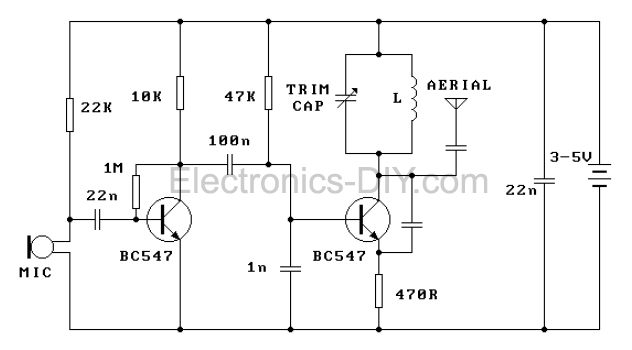
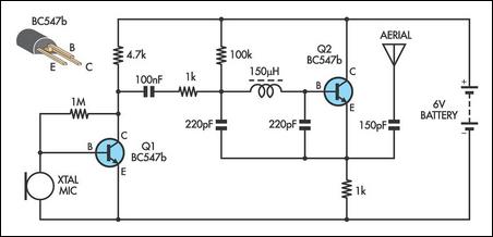
The FM transmitter circuit is an efficient design that leverages a minimal number of components to achieve effective performance. The electret microphone serves as the input transducer, converting sound waves into electrical signals. The audio amplifier stage, built with the first transistor, amplifies these signals before passing them to the modulating transistor. The modulation process is crucial as it allows the audio information to be embedded onto the carrier wave generated by the oscillator circuit.
The Colpitts oscillator configuration is particularly suitable for this application due to its stability and ease of tuning. The resonant frequency is determined by the inductance of the coil and the capacitance of the trim capacitor. Adjusting the spacing of the coil turns can provide an alternative method for tuning if a variable capacitor is not available. This flexibility allows for fine-tuning of the transmitter to achieve optimal performance within the desired frequency range.
The construction on a single-sided PCB simplifies assembly and reduces the risk of errors during the build process. The layout should be designed to minimize interference and ensure that the components are placed in a manner that facilitates proper signal flow. The use of a half or quarter wavelength antenna is critical for maximizing transmission range and efficiency. The antenna should be constructed from suitable wire material to ensure good conductivity and should be securely connected to the aerial point on the PCB.
It is imperative to adhere to local regulations regarding FM transmission to avoid legal complications. Users are encouraged to familiarize themselves with the laws governing wireless transmission in their area to ensure compliance and safe operation of the FM transmitter.This FM transmitter is about the simplest and most basic FM transmitter it is possible to build and have a useful transmitting range. It is surprisingly powerful despite its small component count and 3V operating voltage. It will easily transmit over 300 meters in the open air and even more with higher voltage supply. The circuit we use is based o n a proven Australian design. It may be tuned anywhere in the FM band. Or it may be tuned outside the commercial M band for greater privacy. Of course this means you must modify your FM radio to be able to receive the transmission or have a broad-band FM receiver. The output power of FM transmitter is within the legal limits of many countries. However, some countries may ban all wireless FM transmitters without a licence. It is your responsibility to check the legal requirements for the operation and to obey them. FM transmitter is constructed on a single-sided printed circuit board PCB. Components may be added to the PCB in any order. Note that the electret microphone should be inserted with the pin connected to the metal case connected to the negative rail (that is, to the ground or zero voltage side of the circuit).
The coil should be about 3mm in diameter and 5 turns. The wire is tinned copper wire, 0. 61 mm in diameter. After the coil in soldered into place spread the coils apart about 0. 5 to 1mm so that they are not touching. (The spacing in not critical since tuning of FM transmitter will be done by the trim capacitor. It is quite possible, but not as convenient, to use a fixed value capacitor in place of the trimcapacitor - say 47pF - and to vary the Tx frequency by simply adjusting the spacing of the coils. That is by varying L of the LC circuit rather than C. ) Adding and removing the batteries acts as a switch. Connect a half or quarter wavelength antenna (length of wire) to the aerial point. At an FM frequency of 100 MHz these lengths are 150 cm and 75 cm respectively. This FM transmitter is about the simplest and most basic FM transmitter it is possible to build and have a useful transmitting range.
It is surprisingly powerful despite its small component count and 3V operating voltage. It will easily transmit over 300 meters in the open air and even more with higher voltage supply. The circuit we use is based on a proven Australian design. It may be tuned anywhere in the FM band. Or it may be tuned outside the commercial M band for greater privacy. Of course this means you must modify your FM radio to be able to receive the transmission or have a broad-band FM receiver. The output power of FM transmitter is within the legal limits of many countries. However, some countries may ban ALL wireless FM transmitters without a licence. It is your responsibility to check the legal requirements for the operation and to obey them. FM transmitter is constructed on a single-sided printed circuit board PCB. The circuit is basically a radio frequency (RF) oscillator that operates around 100 MHz. Audio picked up and amplified by the electret microphone is fed into the audio amplifier stage built around the first transistor.
Output from the collector is fed into the base of the second transistor where it modulates the resonant frequency of the tank circuit (the 5 turn coil and the trimcap) by varying the junction capacitance of the transistor. Junction capacitance is a function of the potential difference applied to the base of the transistor.
The tank circuit is connected in a Colpitts oscillatorcircuit. Let us look at the individual blocks of the circuit more closely: The electret microphone: an electret is a permanently charged dielectric. It is made by heating a ceramic material, placing it in a magnetic field then allowing it to cool while still in the magnetic field.
It is the electrostatic equivalent of a permanent magnet. In the electret microphone a slice of this material is used as part of the dielectric of a capac 🔗 External reference
Related Circuits
Construct this circuit utilizing a Digi-Key Electronics Barrel Crystal (CA-301) with a frequency of 15 MHz to achieve a standard output frequency of 150.00 MHz. For frequency customization, follow the provided instructions. Typically, this circuit is designed to operate...
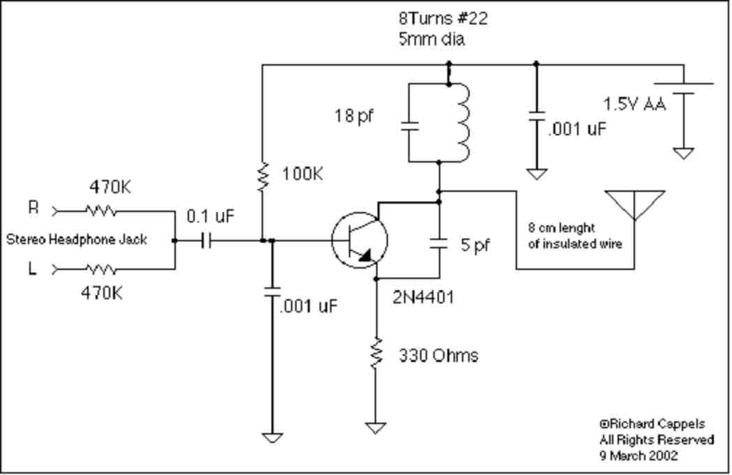
This implementation is adapted to rebroadcast the output of a CD player, television receiver, or radio receiver. I use it so that I can move about the house and listen to my favorite programs without disturbing others. Within the...
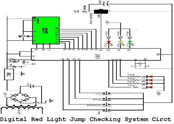
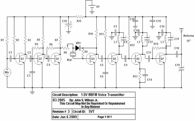
A digital red light jump checking system with an RF transmitter. This project allows for the tracking of vehicles that run red lights by capturing their license plate numbers and the time of the violation. The digital red light jump...
The following circuit illustrates the IC BA1404 used in a stereo FM transmitter circuit diagram. Features include ease of construction, making it accessible for anyone to build. The BA1404 is a versatile integrated circuit designed specifically for FM transmission applications....
This AM transmitter is designed for simplicity, featuring an untapped inductor with a single winding. The inductor can be easily sourced as a standard RF choke, such as the Jaycar Cat LF-1536. To minimize the circuit size, a conventional...
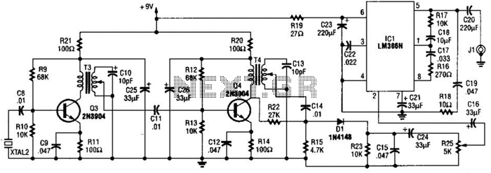
The 2.25-MHz oscillator Q1 drives amplifier Q2 and XTAL1, an ultrasonic transducer. The transducer is a lead zirconate-titanate type. Taps on T1 and T2 provide low-impedance drive points. The circuit consists of a 2.25-MHz oscillator (Q1) that serves as the...