
FM Transmitter
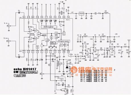
The transmitter circuit is designed to operate efficiently with a 9V power supply, making it suitable for portable applications. The use of three separate transmitter circuits allows for enhanced signal clarity and reduces the likelihood of interference, which is particularly important in environments with multiple audio sources. The mixer connected to the receivers enables seamless integration of the transmitted signals, ensuring that the choir's performance is captured accurately.
Capacitor C3 plays a vital role in maintaining the stability of the circuit by preventing oscillations that could lead to signal distortion. The design's reliance on NPN transistors offers advantages in terms of switching speed and gain, contributing to the overall performance of the transmitter.
The inductance of L1 can be calculated using the formula for a solenoid, which considers the number of turns, the length of the coil, and the diameter. This calculation is essential for determining the resonant frequency of the circuit, which directly impacts the quality of the transmitted audio signal. Proper tuning of L1 is critical to achieving optimal performance, ensuring that the transmitter operates within the desired frequency range for FM transmission.
Overall, this transmitter design represents a practical solution for enhancing audio quality in live performance settings, addressing the specific needs of the choir and congregation while ensuring reliability and clarity in sound reproduction.This simple transmitter operates from a 9V battery as shown above. I personally built this for a purpose. This is how it happened:- "members of my singing group find it difficult to handle a FM mic in Church. The choir sings in acapella form and the congregation expect us to perform well. The old FM mic system was not a perfect solution, so I buil t this kit and a mixer for the receivers. using three separate transmitter circuits and a mixer on the receiever, the choir voices were perfect and cleanly reproduced. " From the notes I made experimentally, C3 is vital to the circuit and without it the circuit may become unstable.
C4 is in parallel with C5 and presents a moderate load impedance. Finally all transistors are NPN. The circuit works well and has proved reliable. Using the above values, the inductance of L1 can be calculated. A diameter of 5. 5mm = 0. 22 inches, the radius is half this value or 0. 11 inch, the length is 4. 5mm and number of turns, n = 6. This gives L1 a value of: 🔗 External reference
Related Circuits
This schematic represents an FM transmitter that delivers an output power of 3 to 3.5 watts, operational within the frequency range of 90 to 110 MHz. While the stability of the circuit is acceptable, incorporating a Phase-Locked Loop (PLL)...
A basic circuit of the transistor UHF radio transmitter with a surface acoustic wave resonator (SAW) is presented. The SAW is utilized as a positive feedback element connected between the transistor's base and an LC network in parallel. In...
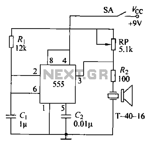
The circuit comprises an ultrasonic transmitter and a T-4 0-16 555 timer circuit. By adjusting the potentiometer RP, the frequency of the oscillation circuit can be modified. The circuit emits ultrasonic signals at a frequency of 40 kHz, with...
Operating radio transmitters without a license is illegal in most countries, so caution is advised with transmitter circuits. This FM low-power circuit is designed to operate within the 87-108 MHz band II, providing a range of approximately 20 to...
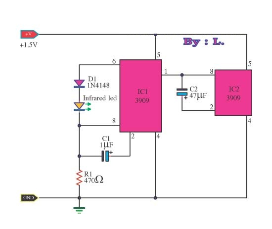
This circuit is an infrared transmitter that operates on a low power supply of 1.5 V. The main components include two LM3909 integrated circuits, which function as an oscillator and LED flasher. Typically, this circuit is utilized as a...
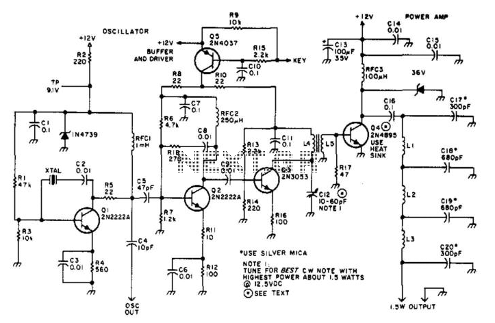
Suitable for amateur use, this 1.5-W transmitter operates on a 12-V supply. Q1 functions as an oscillator utilizing a surplus FT243 crystal. Q2 serves as a buffer driver and is activated through the keying transistor Q5. Q3 acts as...