
FM Transmitter

The described low-power FM transmitter is designed for short-range audio transmission, suitable for applications such as personal broadcasting or educational projects. The schematic typically includes a power supply section, an oscillator circuit, an amplifier stage, and an output stage for modulation.
The transmitter operates efficiently at voltages of 9V and 12V, with the increased voltage resulting in a notable enhancement in transmission range. The specified range of 300 feet at 9V and 400 feet at 12V indicates that the transmitter is optimized for low-power applications while still providing adequate coverage.
Coils L1 and L2 are critical components in the oscillator circuit. They are constructed from 28 AWG enamel-coated magnet wire, which is suitable for RF applications due to its lower resistance and ability to handle high frequencies. The coils should be wound with 5 turns, ensuring that the inductance is within the required specifications for the oscillator circuit to function correctly. The use of a ballpoint pen tube as a winding form is a practical and accessible method for achieving the desired coil dimensions, with an inside diameter of approximately 4mm. After winding, it is essential to remove the form to allow for proper installation on the printed circuit board (PCB).
The PCB design will include designated areas for all components, including the coils, resistors, capacitors, and any integrated circuits used in the transmitter. Proper placement of components is crucial to minimize interference and ensure optimal performance. The layout should also consider the RF characteristics of the circuit, including trace width and length, to avoid signal loss and maintain signal integrity.
In summary, this low-power FM transmitter schematic provides a foundation for a compact and efficient broadcasting solution, with specific construction techniques for key components that enhance performance and reliability.Here is the schematic, PC board pattern, and parts placement for a low powered FM transmitter. The range of the transmitter when running at 9V is about 300 feet. Running it from 12V increases the range to about 400 feet. This transmitter should not be used as a room or telephone bug. # L1 and L2 are 5 turns of 28 AWG enamel coated magnet wire wound with a inside diameter of about 4mm. The inside of a ballpoint pen works well (the plastic tube that holds the ink). Remove the form after winding then install the coil on the circuit board 🔗 External reference
Related Circuits
This circuit allows for the construction of a compact tracking transmitter that can be detected using an FM broadcast band radio receiver. The transmitter operates on a power source of any 1.5V battery or power supply. It has a...
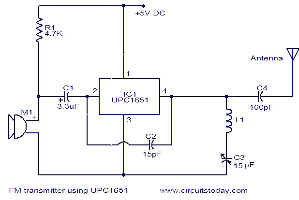
The circuit diagram of an FM transmitter utilizes the IC UPC1651, which is a wideband UHF Silicon MMIC amplifier. This integrated circuit features a broad frequency response of up to 1200 MHz and a power gain of up to...

The transmitter utilizes a 6BW6 vacuum tube to achieve an output power of approximately 5 watts. The circuit includes a component CI that is calibrated to produce the cleanest continuous wave (CW) note. The tuning capacitors C8 and C9...

The pressure transmitter circuit data acquisition system utilizes the 1B31, an 18-bit A/D converter (AD1170), and an MCS-51 microcontroller. The configuration, as depicted in the accompanying diagram, features a full-scale output voltage of 10 mV from the pressure transmitter...
L1 is 0.112uH (this tunes to the middle of the FM band, 98 MHz, with VC1 at its centre value of 33pF). L1 is 5 turns of 22 swg enamelled copper wire close-wound on a 5mm (3/16") diameter former....

The following circuit illustrates a simple TV transmitter circuit diagram. This circuit is based on the LM1889 integrated circuit (IC). Features include quadrature chroma modulators and RF capabilities. The circuit utilizes the LM1889 IC, which is designed for television applications,...