
Voltage monitor circuit
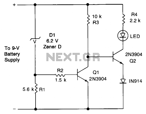
The described circuit employs a Zener diode (D1) to create a voltage reference point at 9 V. This component is critical in monitoring the voltage level of the battery. When the battery voltage is above 9 V, D1 remains in a conducting state, allowing current to flow through Q1, keeping it in the 'on' state. This action ensures that the output remains stable and does not trigger any warning signals.
As the battery discharges and the voltage drops to 7 V, D1 will no longer conduct. This cessation of current flow causes Q1 to turn off, which results in an increase in the collector voltage of Q1. The increased voltage at the collector will forward-bias Q2, allowing it to conduct. This conduction of Q2 activates LED1, providing a visual indication that the battery voltage has fallen below the critical threshold.
Resistor R4 is incorporated in series with LED1 to limit the current flowing through the LED, thereby protecting it from excessive current which could lead to failure. The choice of resistor value is essential to ensure that LED1 operates within its specified current range.
This circuit is particularly useful in battery-operated devices where monitoring battery health is crucial for reliable operation. By providing an early warning signal, it allows users to take action before the battery voltage drops to a level that could lead to device malfunction or damage.This circuit gives an early warning of the discharge of batteries. Zener diode Dl is chosen for the voltage below which an indication is required (9 V). Should the supply drop to below 7 V, Dl will cease conducting causing Ql to shut off. Its collector voltage will now increase causing Q2 to start conducting via LED1 and its limiting resistor R4. 🔗 External reference
Related Circuits
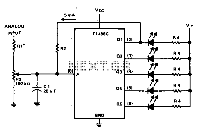
This circuit offers a visual representation of the input analog voltage level. It features a high input impedance at pin 8 and open-collector outputs that can sink up to 40 milliamperes. It is designed to drive a linear array...
The LM1036 is a DC-controlled circuit designed for adjusting bass, treble, balance, and volume in stereo applications, particularly in car radios, televisions, and audio systems. An additional control input enables the implementation of loudness enhancement. Four control inputs facilitate...
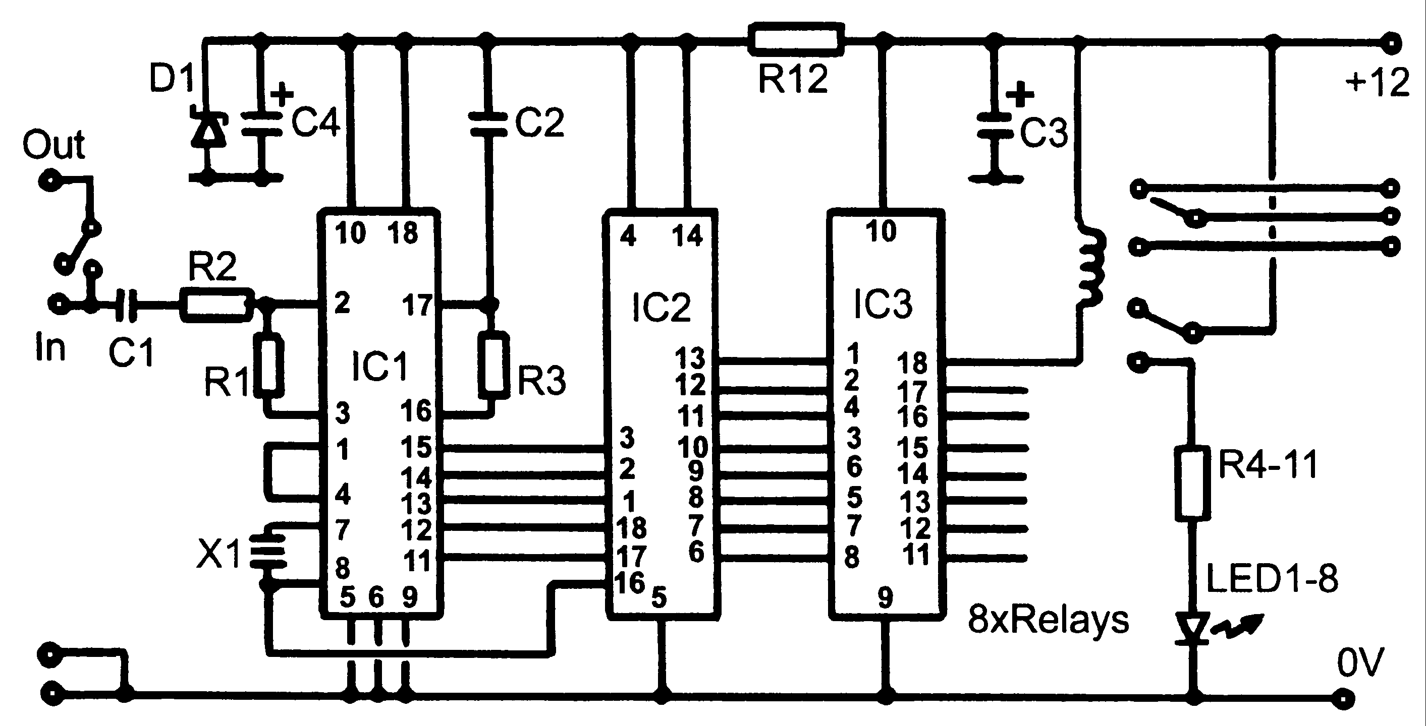
Control monitoring equipment at a TV repeater site is designed to accept commands sent as DTMF tones over the repeater's audio channel. It is capable of switching either AV signals or power supply feeds with currents up to 1...
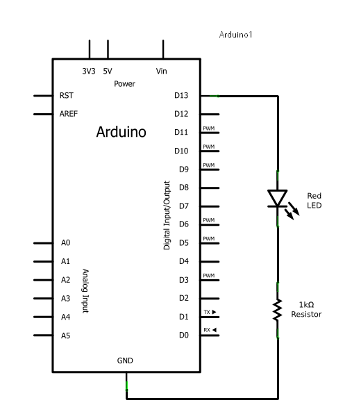
Arduino consists of two main components: the hardware (the Arduino board) and the software (the IDE). The advantage of using Arduino is that circuits can be built and their behavior modified by altering the code instead of changing the...
This circuit provides an initial voltage of 2.5V per cell to quickly charge a car battery. The charging current decreases as the battery charges, and when the current drops to 180 mA, the charging circuit reduces the output voltage...
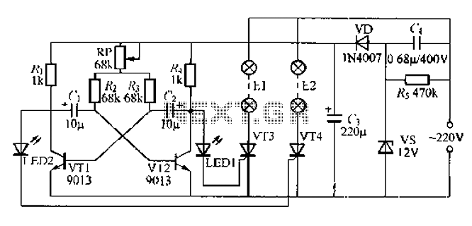
The circuit utilizes a thyristor-controlled unidirectional flashing light string controller. Diodes VT1 and VT2 are connected to a multi-oscillator. Upon powering the circuit, VT1 and VT2 alternately turn on and off. When VT1 is deactivated, VT2 is powered by...