
Inverter circuit diagram
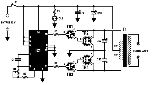
The described circuit incorporates several key components and configurations essential for its operation. The power transistors TR2 and TR4, which are critical for managing the output power, require adequate thermal management through the use of heatsinks. This ensures that they operate within safe temperature limits, thus enhancing the reliability and longevity of the circuit. The choice of MJ4033 or MJ3007 transistors is based on their NPN characteristics and ability to handle the specified power levels.
The transformer T1 plays a pivotal role in determining the overall power output of the inverter circuit. The specified VA ratings (50 VA and 90 VA) indicate the maximum load that can be handled safely, with the secondary output voltage set at 230 V. The current ratings highlight the relationship between the transformer size and the load's power requirements, emphasizing the importance of selecting an appropriately rated transformer for the intended application.
The inverter circuit utilizes the CMOS 4047 integrated circuit, which is configured as an astable multivibrator. This configuration is crucial for generating the necessary square wave signal that drives the power transistors, enabling the conversion of DC to AC. The adjustable resistor R1 allows for fine-tuning of the oscillator frequency, which can affect the output waveform and efficiency of the inverter.
In addition to the inverter functionality, the circuit also serves as a motorcycle battery charger. The design focuses on delivering a low charge current, which is vital for maintaining the health of motorcycle batteries and preventing damage to the battery plates, thereby extending their service life.
The isolated power supply circuit, capable of providing 5 V to 15 V at 500 mA, is designed for versatility and ease of integration into various applications. This circuit exemplifies a classic approach to power supply design, utilizing readily available components to achieve reliable performance.
Furthermore, the simple switching power supply is capable of powering loads up to 20 watts while maintaining a compact form factor. This is particularly advantageous in applications where space is at a premium. The DC power supply circuit, designed for a stable output voltage range of 3 to 30 V, is suitable for a wide range of electronic projects, as long as the current draw remains within the specified limits.
Overall, the described circuits are versatile and can be adapted for various applications, demonstrating the importance of careful component selection and circuit design in achieving desired performance outcomes.The two final power of TR2-TR4 should be mounted on heatsink the right size, otherwise they will overheat. You can choose from MJ4033 MJ3007 or more, provided that the NPN. The maximum power output that can be used depending on the size of the core of the transformer T1, the VA is: with 50 VA can be taken in the secondary 230 V 0.
2 A (current consumed by the end will be 4 A) with 90 VA can be taken on the secondary 230 V 0. 4 a (current consumed by the end will be 7 A). The schematic diagram come from circuit: Converter 12 Vdc to 230 Vac or Inverter power supply. Go to that page to read the explanation about above power supply related circuit diagram. As shown in the Inverter circuit diagram obove, Its used as the oscillator stage astable multivibrator contained in IC1, a CMOS 4047 (this cult series 40xx series) by varying the resistance value of R1 trimmer (220 k total resistance). The above scheme is a motorcycle battery charger, which is intended only for charging motorcycle batteries as its has a low charge current and thereby saving the battery plate from premature failure.
This motorcycle battery charger circuit generate current of. The Isolated Power supply 5 V to 15 V, 500 mA diagram represents a single control block, knowing that all are identical. It is truly classic, and is based on the use of common components. The Isolated Power supply 5. This Simple switching power supply for 15 Watt can be used to power any load up to 15. 20 watts and has smaller dimensions than a similar, but with the step-down transformer, operating at a frequency of 50 Hz.
. This DC power supply circuit diagram is designed as an additional or as a permanent power supply for all general circuits based on a stable DC voltage between 3 and 30V provided that current consumption does not exceed 3A. Of. We aim to transmit more information by carrying articles. Please send us an E-mail to wanghuali@hqew. net within 15 days if we are involved in the problems of article content, copyright or other problems.
We will delete it soon. 🔗 External reference
Related Circuits
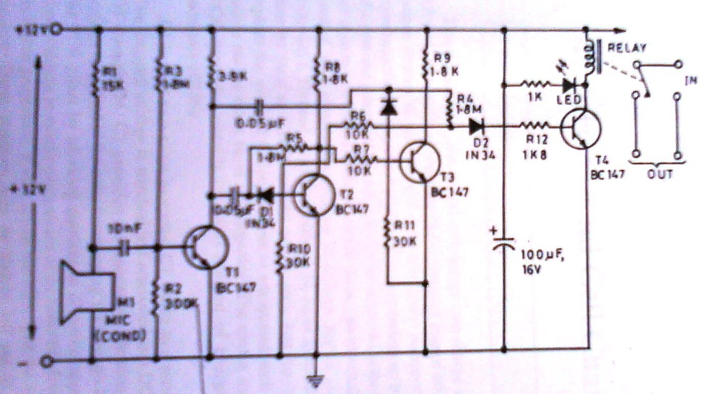
This clap switch can turn on and off a light, fan, music system, or alarm—virtually any gadget—at the sound of a clap. The most remarkable feature of this design is its ability to provide efficient two-state control without the...
The bearing fault detector circuit consists of a bearing detection sensor, a signal processing circuit, a transistor (V), an audio amplifier integrated circuit (IC2), a speaker (BL), an RC element, an integrated circuit (IC1), and a light-emitting diode (VL)....
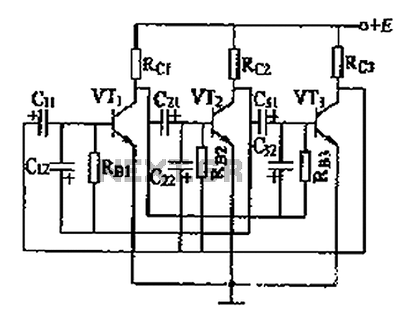
The three astable circuit is illustrated, demonstrating that each level of the transistor's base is connected by a capacitor between the two levels, ensuring tight coupling. Additionally, each base electrode is biased through a resistor (Rb) connected to the...
A gas leak detector circuit that detects the leakage of LPG gas and alerts the user through audio-visual indications. The circuit operates off a 9V PP3 battery. A Zener diode is used to convert 9V into 5V DC to...
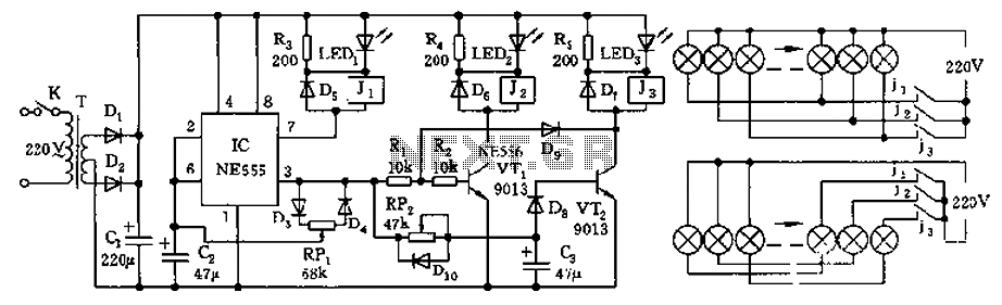
The controller features a buck rectifier circuit utilizing a 555 multivibrator, designed for controlling approximately 220V, 5W low-power parallel lights or 6 to 12V small bulb series. The 555 timer, along with components D3, D4, RP1, and C2, forms...

This design circuit is for a simple 27MHz transmitter that produces a carrier signal. The circuit generates an unmodulated 27MHz signal, which can be received by a compatible receiver. The transmitter operates as a basic crystal oscillator, with the...