
Peak Detector Circuit
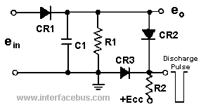
The waveforms associated with this circuit illustrate an amplitude-modulated signal detected by the diode and then envelope detected by the capacitor. An upgraded version of the peak detector, which utilizes additional components, serves as a pulse amplitude demodulator. The same waveforms apply, although PAM typically involves a single polarity. Diode CR1 performs the same function as before, allowing capacitor C1 to charge while a positive pulse is applied. When the incoming pulse returns to zero volts, CR1 becomes reverse biased, isolating the detector from the input. Diodes CR2 and CR3 are reverse biased and non-conducting due to the positive voltage applied to Ecc. Capacitor C1 charges through diode CR1, with its time constant determined by CR1's resistance and C1. The capacitor discharges through resistor R1, establishing a different time constant. The resistor and capacitor values are selected to ensure the RC time constant is ten times the period between pulses, preventing the capacitor from fully discharging between pulses and maintaining voltage. Just before the next incoming pulse, the capacitor discharges through CR2 and CR3 due to the negative-going discharge pulse, allowing rapid discharge through the forward-conducting CR2 diode. Diode CR3 ensures that the output voltage remains one diode drop above ground. The third waveform represents the output voltage after additional filtering, which is not depicted in the circuit diagram. An alternative enhancement to the basic peak detector or envelope detector involves using transistors instead of diodes, as illustrated in a subsequent circuit example featuring a transistor envelope detector.
The peak detector circuit can be realized using a minimal arrangement of components, primarily focusing on the diode, capacitor, and resistor. The diode serves to rectify the incoming signal, allowing only the positive half-cycles to pass through. The capacitor, connected in parallel with the load, charges to the peak voltage of the incoming signal, while the resistor provides a discharge path for the capacitor, creating a time constant that dictates how quickly the capacitor can discharge. This time constant is critical in ensuring that the capacitor retains sufficient charge between incoming pulses, effectively smoothing the output signal.
In the upgraded pulse amplitude demodulator configuration, the inclusion of additional diodes (CR2 and CR3) enhances the functionality of the circuit, allowing for better isolation and control over the discharge process. The careful selection of component values is essential to optimize the performance of the circuit, ensuring that it can accurately track the incoming waveform without significant distortion. The use of transistors in subsequent designs can further improve the efficiency and responsiveness of the detector, providing a more robust solution for applications requiring precise peak detection and demodulation of amplitude-modulated signals.A Peak Detector is any circuit that functions to detect the peak voltage of an incoming waveform. Basically the circuit is used as an Amplitude Modulation [AM] detector, Pulse Amplitude Modulation [PAM] detector or Envelope detector. The particular circuit covered in this topic is the diode detector, in its basic form. The most basic form of a pea k detector uses a single diode to limit current flow in only one direction and a capacitor which charges up to the highest voltage applied to it [the peak voltage]. A resistor is than added to provide a discharge path for the capacitor. Of course the circuit is using the minimum number of parts. However the peak detected voltage will always be one diode drop below the actual incoming voltage peak.
The capacitor may leak, and not stored, or hold the maximum voltage applied to it, and the discharge time of the capacitor needs to occur before the next incoming peak. That is the RC time constant needs to be selected to match the incoming signal, so the capacitor will charge through the diode [Dr x C] and discharge through the resistor [R x C].
However your not likely to see this circuit used, other than in a lab experiment, but you should still find it in text books. The waveforms to the right are just an example of an amplitude modulated signal, which is detected by the diode, and than Envelope detected by the capacitor.
The next circuit is an upgrade, of the same approach, using a few more components of course. This next circuit is an example of a peak detector used as a pulse amplitude demodulator. The same waveforms to the right still apply, although PAM is normally just a single polarity. Diode CR1 performs the same function as before and allows capacitor C1 to charge while a positive pulse is applied to the circuit. When the incoming pulse falls back to zero volts, CR1 becomes reverse biased and the detector is isolated from the input.
Diodes CR2 & CR3 are reversed biased, and non-conducting, due to the positive voltage applied to Ecc. Capacitor C1 charges through diode CR1 [the ON resistance of the conducting diode], so the time constant is CR1r x C1.
The capacitor discharges through R1, so that time constant is R1 x C1. Read more on the Definition of Time Constant. The values of the resistor and capacitor, which produce the RC time constant are selected so that the time constant is 10 times the period between pulses. So the capacitor is not allowed to fully discharge in between pulses, and so maintains a voltage. Just before the next incoming pulse the capacitor is allowed to discharge through CR2 and CR3 by the application of the negative going discharge pulse.
The capacitor is allowed to quickly discharge through the forward conducting CR2 diode. Diode CR3 insures that the output voltage is just one diode drop off ground. The third waveform to the right would be the approximation of the output voltage after some additional filtering, which is not shown in the circuit diagram. An additional upgrade to the basic peak detector, or envelope detector would be to use transistors instead of diodes.
This next circuit example shows a Transistor Envelope Detector. 🔗 External reference
Related Circuits
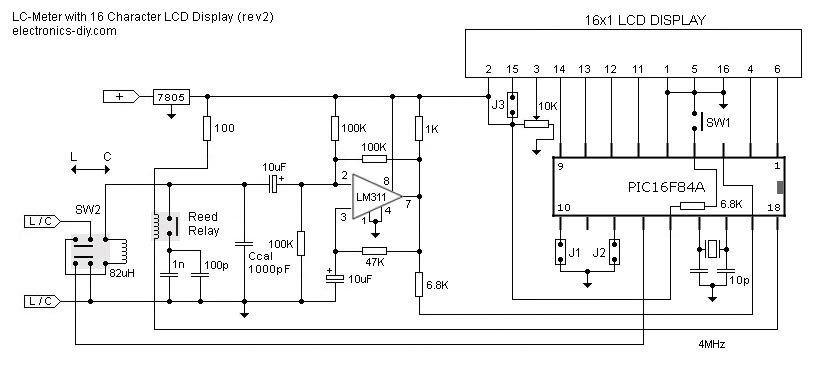
This is one of the most accurate and simplest LC inductance/capacitance meters available, which can be easily constructed by an individual. This LC meter is capable of measuring very small inductances ranging from 10 nH to 1000 nH, 1...
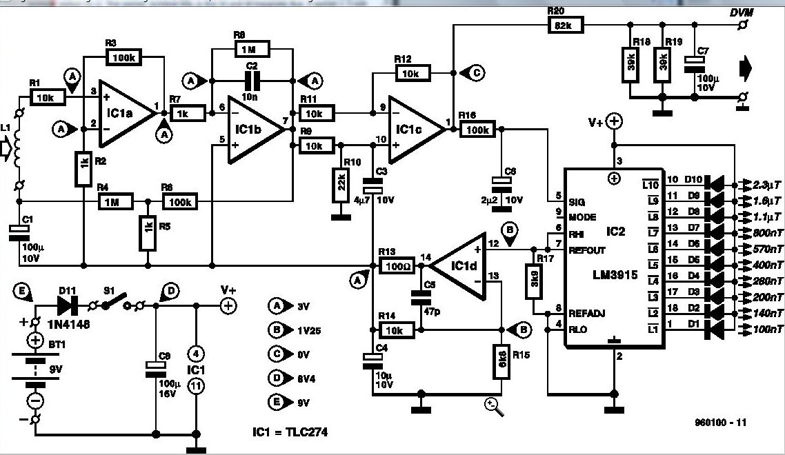
Some experts believe that static magnetic fields (SMFs) may affect the physical well-being of individuals. If one subscribes to this viewpoint, the magnetic-field meter described here will aid in locating sources of SMFs and assessing their strength. These results...
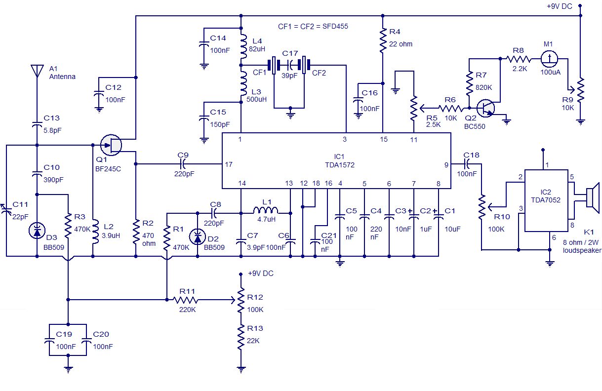
High-quality AM radio circuit based on the TDA1572 IC. The AM radio receiver circuit operates from 9V DC and has a 1W output power. It requires a minimum number of external components. The AM radio circuit utilizing the TDA1572 integrated...
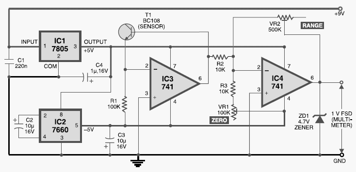
This digital thermometer circuit diagram uses a common 1N4148 diode as the temperature sensor. The temperature coefficient of the diode is -2 mV/°C. The digital thermometer circuit leverages the characteristics of the 1N4148 diode, which has a well-defined temperature coefficient....
This circuit is designed to indicate, via a flashing LED, when room noise exceeds a predetermined threshold, selectable from three fixed levels: 50 dB, 70 dB, and 85 dB. The circuit utilizes two operational amplifiers to amplify the sound...
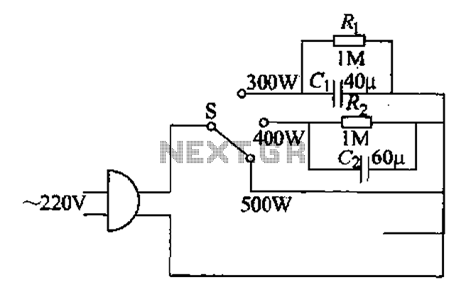
Each family has essential small appliances. The sub-type is an electric power jet, mainly used for clothes and hot shaping. The iron's circuit is shown in Figure 1-30. When using an iron, there is always a concern about using...
Warning: include(partials/cookie-banner.php): Failed to open stream: Permission denied in /var/www/html/nextgr/view-circuit.php on line 713
Warning: include(): Failed opening 'partials/cookie-banner.php' for inclusion (include_path='.:/usr/share/php') in /var/www/html/nextgr/view-circuit.php on line 713