
FM Transmitter Using Logic Gates

The FM transmitter circuit is designed to modulate audio signals onto a carrier frequency for transmission over radio waves. The core component of this circuit is the RF oscillator, which generates a stable 10.7 MHz frequency. This frequency is typically chosen for its compatibility with common FM radio band frequencies, allowing for effective transmission.
The logic gates in the circuit serve various functions, including signal processing and modulation. These gates can be implemented using CMOS or TTL technology, depending on the design requirements. The oscillator's output is fed into the modulation stage, where the audio input signal is combined with the carrier wave. This is typically achieved through a mixer circuit that uses diodes or transistors to effectively superimpose the audio signal onto the carrier frequency.
The ceramic filter plays a crucial role in ensuring that the output signal is clean and free from unwanted harmonics or spurious signals. Operating at 10.7 MHz, the filter allows the desired frequency to pass while attenuating others, ensuring compliance with regulatory standards for FM transmission.
Power supply considerations are also essential in the design of the FM transmitter. A regulated power supply is recommended to maintain consistent performance, particularly in the RF oscillator stage. Additionally, the output stage may incorporate an amplifier to boost the signal strength before transmission, allowing for greater range and clarity.
Overall, this FM transmitter circuit represents a straightforward yet effective design for wireless audio transmission, utilizing fundamental electronic components and principles. Proper tuning and antenna design will further enhance the performance and range of the transmitter, making it suitable for various applications in amateur radio, educational projects, and low-power broadcasting.This is a FM Transmitter circuit. This circuit uses logic gates. This transmitter circuit has a RF oscillator. This oscillator uses 10.7Mhz ceramic filter and. 🔗 External reference
Related Circuits
This schematic represents an FM transmitter capable of delivering an output power between 3 to 3.5 W, operating within the frequency range of 90 to 110 MHz. While the stability of the circuit is acceptable, the integration of a...
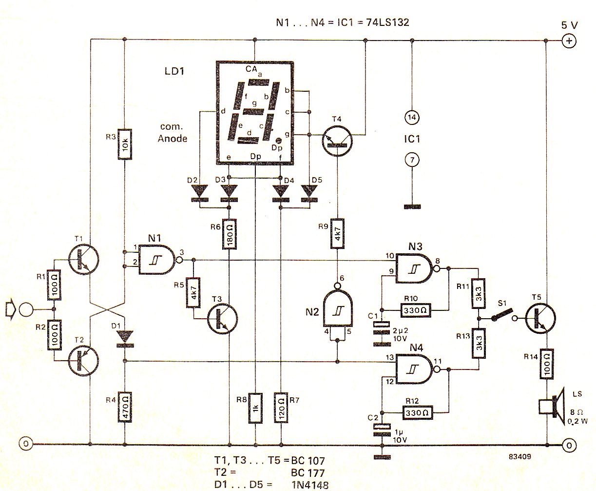
When the input signal is at logic high (1), the display indicates `H`, and the loudspeaker emits a note that is one octave higher than the low tone. The operation of the circuit can be observed in the circuit...
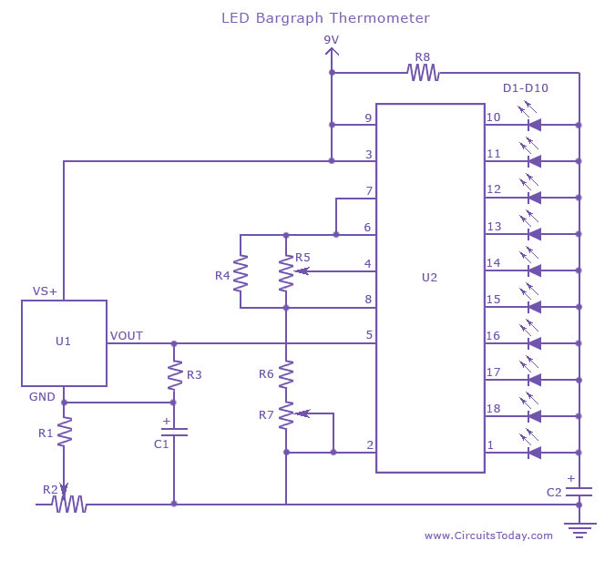
An LED thermometer that can function as a temperature sensor or temperature measurement circuit, utilizing the LM34 for Fahrenheit display or the LM35 for degree Celsius display. The LED thermometer circuit is designed to provide accurate temperature readings using either...

The 1-Wire Net, or MicroLAN (by Maxim-Dallas), is a straightforward method for connecting slow devices such as sensors, relay drivers, and switches using basic components. These components include a 1-Wire protocol handler, an interface to the external world, and...
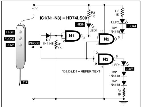
A TTL logic probe is an essential tool for troubleshooting digital circuits. Various methods can be utilized to design a logic probe. The most common designs incorporate operational amplifiers, logic gates (OR, NOT, XOR), and transistors. The circuit described...
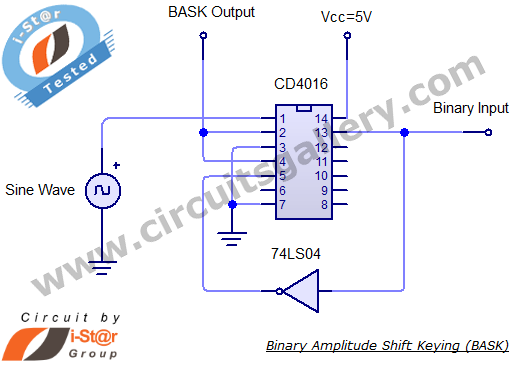
Binary Amplitude Shift Keying (BASK), also known as On-Off Keying (OOK), is a digital modulation technique where the amplitude of the carrier signal is altered according to binary data. This modulation scheme is utilized for transmitting digital information over...