
FM voice transmitter for Band 2 VHF
The transmitter circuit operates based on the principles of a Hartley oscillator, which is characterized by its ability to generate radio frequency signals. The oscillator consists of an inductor and capacitor forming a resonant tank circuit. In this specific design, the tank circuit is integral to the oscillator's performance, and the choice of components is crucial for achieving the desired frequency stability and output power.
The four turns of 18 SWG wire form the inductor, which is wound around a quarter-inch former. This physical configuration is important as it helps to establish the inductance required for the oscillator to function effectively at VHF frequencies. The use of 18 SWG wire is beneficial due to its balance between resistance and inductance, allowing for efficient energy transfer within the circuit.
The aerial tap, located one and a half turns from the supply end, serves as the point where the RF signal is coupled out to the antenna. This tap is critical for optimizing the transmission efficiency and ensuring that the signal strength is adequate for the intended range. The positioning of the tap can significantly influence the impedance seen by the oscillator, thus affecting the overall performance of the transmitter.
In terms of audio input, the transmitter is designed to work effectively with ECM-type microphones, which are known for their high sensitivity and low noise characteristics. This compatibility enhances the quality of the transmitted audio signal, making it suitable for various applications, such as broadcasting or communication in VHF ranges.
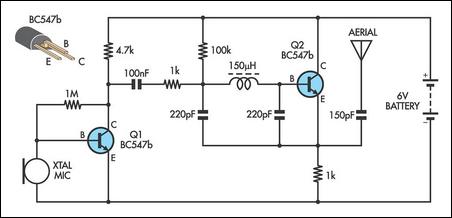
Overall, this small transmitter design demonstrates a practical approach to RF signal generation, leveraging the Hartley oscillator topology and carefully selected component specifications to achieve reliable performance in VHF applications.This small transmitter uses a hartley type oscillator. Normally the capacitor in the tank circuit would connect at the base of the transistor, but at VHF the base emitter capacitance of the transistor acts as a short circuit, so in effect, it still is. The coil is four turns of 18swg wire wound around a quarter inch former. The aerial tap is about one and a half turns from the supply end. Audio sensitivity is very good when used with an ECM type microphone insert. 🔗 External reference
Related Circuits
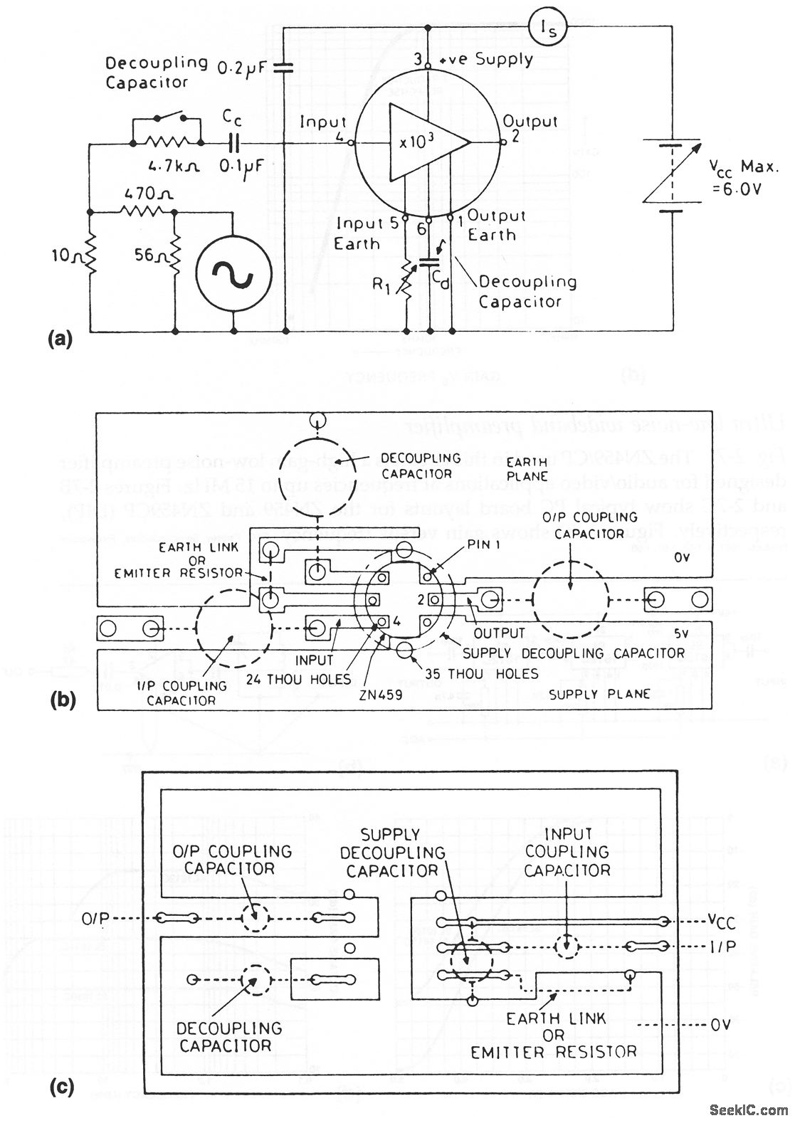
The ZN459/CP utilized in this circuit is a high-gain, low-noise preamplifier intended for audio and video applications at frequencies reaching up to 15 MHz. Figures 2-7B and 2-7C illustrate typical printed circuit board layouts for the ZN459 and ZN459CP...
Maxim has introduced a series of five integrated oscillator building blocks in the MAX260x series, covering a frequency range of 45 to 650 MHz. The MAX2606 is designed for the VHF band, allowing frequency variation of approximately ±3 MHz...
This AM transmitter is designed for simplicity, featuring a non-tapped inductor with a single winding. The inductor is a standard RF choke, such as the Jaycar Cat LF-1536, eliminating the need for custom winding. To minimize the circuit's size,...
An FM transmitter circuit that utilizes a low power configuration, employing an operational amplifier as an audio preamplifier and a single transistor to function as the RF amplifier. This FM transmitter circuit is designed for low power applications, making...

In order to simplify the transmitter design, we've used the new pll circuit from Motorola: the MC145170. This PLL includes the prescaler and a serial standard bus called SPI. We advise to use the P2 version that fixes some...
This circuit illustrates a 6-12 channel TV transmitter coupling circuit diagram. It is designed to stabilize the 10 P operation within the 6-12 channel range. The 6-12 channel TV transmitter coupling circuit is essential for ensuring stable transmission across multiple...