
fm wireless microphone schematic
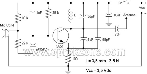
The FM wireless microphone circuit is an efficient solution for applications where mobility is essential. The choice of the 2SC829 transistor is crucial, as it provides adequate amplification while operating at low voltage, which is ideal for battery-powered devices. The use of ceramic capacitors ensures stability and reliability in the circuit, especially in the high-frequency FM range.
The PCB layout, at a compact size of 0.8 x 5 cm, allows for easy integration into various microphone designs, ensuring that the circuitry does not add significant bulk. The antenna design, using a 0.75-meter copper wire, is optimized for both size and performance, allowing the microphone to maintain a good signal quality within its effective range.
The inductor's construction is also a vital aspect of the circuit’s performance. The enamel-coated wire not only provides insulation but also helps in maintaining the integrity of the coil's inductance. By adjusting the number of turns and the physical tension of the coil, users can fine-tune the operating frequency to match the desired FM band.
In summary, this FM wireless microphone schematic presents a practical and compact solution for wireless audio transmission, making it suitable for various applications, from public speaking to musical performances, where freedom of movement is a priority. The design emphasizes simplicity and efficiency, ensuring that users can easily replicate and utilize the circuit in their projects.FM Wireless Microphone Schematic. In some applications, the use of the microphone cable is sometimes very difficultly. So use a cordless microphone is needed. Microphone as it is often referred to as wireless microphones (cordless microphone). Here I share wireless microphone circuit schematics using one transistor. Constructed using one bipolar t ransistors and work on the FM band. Resources of the wireless FM microphone circuit is derived from the 1, 5 Volt batteries. Constructed using a single transistor 2SC829 and a few passive components. All capacitors using ceramic materials and resistors using the 1/4 watt to save a FM wireless microphone schematic circuit. Used a single 1. 5 Vdc of battery for power supply. Antenna can be used with a cable 0. 75 meters of length use copper lines made on pcb. The following sightings : Circuit of wireless fm microphone can be made on the of 0. 8 x 5 cm size pcb, so small enough to put on the handle body of microphone. Inductor built it using email wire diameter size of 0. 5 mm by 3. 5 turns. Setting the work frequency of fm wireless microphone made with stretch and tighten the wire coil inductor.
Effective range of wireless microphone above can reach 10 meters in the state of LOS (Line Off Sight) or without obstruction to the FM radio receiver. 🔗 External reference
Related Circuits
A 555 timer can be used to generate a square wave to produce a negative voltage relative to the negative battery terminal. When the timer output at pin 3 goes positive, the series 22 uF capacitor charges through the...
This low-noise microphone amplifier is built with the MAT02 produced by PMI. This microphone amplifier is highly efficient and features a very low noise level. The amplification can be set to either 20 dB or 23.5 dB (10x or...
Most operational amplifier circuits require a dual-polarity power supply - one having +V and -V. However, there are times when a DP supply simply isn't conveniently available. Single-polarity modifications to DP designs often achieve their effect by referencing the...
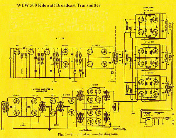
The transmitter was designed with redundancy and cutback (reduced power mode) in mind, giving the transmitter more continuity of service. The final amplifier was divided into 3 separate modules, each using four RCA type UV-898 tubes in push-pull parallel...
Most mobile chargers lack current and voltage regulation as well as short-circuit protection. These chargers supply unregulated 6-12V DC for charging battery packs. Typical mobile phone battery packs are rated at 3.6V and 650mAh. To enhance battery longevity, it...
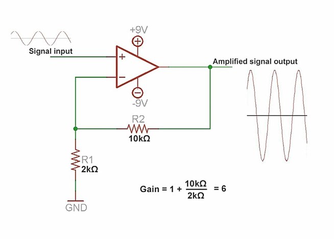
An amplifier is a device that increases the voltage in a circuit. The simplest type is an operational amplifier, and this video will demonstrate how these devices function and how to implement them in electronic applications. As an example,...