
wireless telephone line spy circuit

The phone bug circuit operates by utilizing two transistors to facilitate the transmission of audio signals from a telephone line. The first transistor serves as a switch, controlling the flow of current based on the voltage level detected from the phone line. When the phone is in use, the voltage drops below 15V, which keeps the first transistor in the off state, preventing any interference with the phone line.
Once the first transistor is off, the circuit allows the second transistor to become active. This transistor is configured to oscillate at a frequency around 100MHz, which is suitable for FM transmission. The oscillation generates a modulated signal that carries the audio information from the phone conversation. The modulated signal can then be picked up by a nearby FM radio tuned to the appropriate frequency.
The circuit requires careful design considerations to ensure that it operates effectively without drawing excessive power or causing disruption to the phone line. Proper component selection, including the types of transistors and passive components, is crucial for achieving reliable performance. Additionally, the layout of the circuit should minimize noise and interference, which could degrade the quality of the transmitted audio signal.
For optimal operation, the circuit may also include a power supply regulation component to maintain consistent voltage levels, as well as filtering elements to reduce unwanted signals. Overall, this phone bug circuit exemplifies a simple yet effective method for wireless audio transmission, leveraging basic electronic components to achieve its intended function.Here`s a design of a phone bug circuit. This wireless telephone line spy circuit can be used to transmit the phone conversation to a nearby FM radio. This circuit must connected to a normal phone line. This is the figure of the circuit; The first transistor is turned off, if the voltage drops to less than 15v (if the telephone line is in use).
It w ill enable the second transistor to oscillate at approx 100MHz. Then transmit the phone conversation to a nearby FM radio. 🔗 External reference
Related Circuits

A 1000 Watts audio power amplifier circuit designed for outdoor use. A circuit diagram is needed urgently to facilitate the construction of this high-power amplifier, which is a personal passion project. The design of a 1000 Watts audio power amplifier...
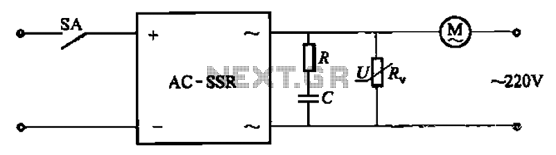
The circuit illustrated in Figure 3-13 is an RC surge absorption circuit that includes a resistor (R) and zinc oxide varistors (such as MY31, MYH12, MYH20 types, etc.), which serve as an overvoltage protection device. The resistance R is...
This circuit produces the famous Big Ben sound. It produces the "ding dong" sound when switched ON. Basically, the circuit alternates between two frequencies which are adjustable. This produces the "ding-dong" sound. The first IC (left) oscillates at about...
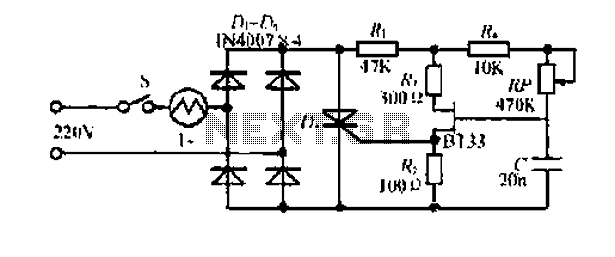
Electrical flow through the saddle j pounds. TV added in a controlled manner Qian Mountain amphipod species lI- ii mi pulsating chord electric. This electric again. The DC Bamboo Division I and the second voltage supply voltage step trigger...
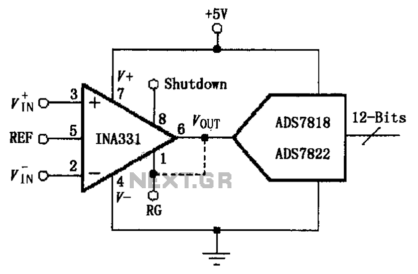
The INA331/332 is configured to directly drive a capacitive input A/D converter. Due to the low output resistance of the INA331/332, it is capable of operating at high frequencies and can directly handle capacitive loads. The output voltage from...

The circuit described can be utilized for tossing a coin, serving as a random generator for head or tail outcomes. This circuit is applicable in various games where a coin toss is required to initiate play. It employs two...
Warning: include(partials/cookie-banner.php): Failed to open stream: Permission denied in /var/www/html/nextgr/view-circuit.php on line 713
Warning: include(): Failed opening 'partials/cookie-banner.php' for inclusion (include_path='.:/usr/share/php') in /var/www/html/nextgr/view-circuit.php on line 713