Plants Humidity Sensor
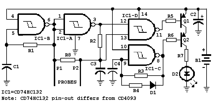
IC1D is a CMOS Schmitt trigger oscillator at about 2KHz. It starts and continues to oscillate with a supply down to 1.24V (the lowest output voltage of my LM317 variable power supply) or less. IC1A is an inverter. IC1B is a Schmitt trigger NAND gate. Its output is low only when both inputs are at, or higher than the upper Schmitt trigger threshold voltage. With 47 ohms or less between the probes, an input is always low, so the output is always high. With a resistance of only R8 between the probes, the voltage across C3 is high most of the time, so the gate's output is low for ½ the oscillator's period. With a resistance that is halfway, then C3 is charged high by that resistance when the oscillator's output is high, then is discharged when the oscillator's output is low. When C3 is being discharged, then pin 12 of the gate is high, and pin 13 is also high until the discharging voltage of C3 reaches the lower Schmitt threshold voltage. During this time, the gate's output is low. So the low time of the gate's output depends on the value of the resistance between the probes. This is Pulse-Width-Modulation of the low output of the gate. IC1C is another CMOS Schmitt trigger oscillator at about 2Hz. D1 and R4 discharge C4 quickly so that its output is low for only about 15ms with a 3V battery, and about 25ms with a 2V battery. The series connection of Q1 and Q2 performs like a NOR gate, so that the LED lights only when both inputs to the transistors are low. R7 is a current-limiting resistor for the 1.8V LED. With a 3V battery, the LED current is about 35mA.
Circuit Operation: When the soil is very dry, the LED flashes brightly, since the soil's resistance is very high. When the soil has been watered a few days before, but is drying, the LED flashes dimly. When the soil is damp because it has been recently watered, the LED is off. Note that different soils have a different resistance. Also, sometimes, watered soil will continue to have a high resistance until the soil absorbs the water, a delay of about one hour. Although the LED's current is 8mA with a 3V battery, it is lighted for only a maximum of only about 1/64th of the time, so its maximum average current is only 550uA. The remainder of the circuit draws 200uA. The total is 750uA for new batteries, and about 250uA for run-down batteries. Therefore the exponential current of 300uA will continue with 1000mA/hr batteries for 2000 hours, or about 4.6 months. The LED's current is logarithmic with the soil's resistance, so that when the resistance is one-half, then the LED's current is one-tenth. If you water the plants when they need watering, then the average LED current will be very low, and the batteries should last for about one year.
Project Assembly: Try to obtain the very bright and wide-angle LEDs that are listed. Samples are available from Fairchild. Use tinned copper 1.5mm diameter buss-bar wire about 8cm long for the probes. Use silicone caulking to attach and seal the Veroboard to the battery holder, and to seal the battery holder's contact holes. Perhaps the project can be mounted in a plastic bottle for pills, available from a pharmacy, with the probes sticking out of its lid.
The circuit utilizes a combination of CMOS Schmitt trigger oscillators and logic gates to create a soil moisture sensing device. The primary component, IC1D, operates as a 2 kHz oscillator, functioning effectively even at low supply voltages, such as 1.24V. This oscillator's output is fed into a NAND gate configuration (IC1B), which determines the output state based on the resistance measured between the soil probes. The input resistance plays a critical role in the modulation of the output signal, effectively implementing a pulse-width modulation technique to control the LED indicator.
The secondary oscillator, IC1C, operates at a much lower frequency of approximately 2 Hz, providing a timed output that interacts with the discharge characteristics of capacitor C4, ensuring that the LED indicator operates within defined time constraints based on the battery voltage used. The discharge time of C4 is influenced by the resistor R4, which controls the timing of the LED's low output state.
Transistors Q1 and Q2 are employed in a NOR gate configuration, ensuring the LED only illuminates when both inputs are low, which occurs under conditions of dry soil. The current limiting resistor R7 is crucial in protecting the LED from excess current, allowing for a maximum of 35mA when powered by a 3V battery. The design efficiently manages power consumption, with the LED's average current being significantly lower than its peak value due to the PWM operation, thus extending battery life considerably.
The assembly instructions emphasize the importance of using high-quality components, particularly for the LED, as well as ensuring proper sealing and protection of the circuit within a suitable enclosure, which is essential for outdoor applications where moisture and environmental factors may pose a risk to the circuit's integrity.IC1D is a CMOS Schmitt trigger oscillator at about 2KHz. It starts and continues to oscillate with a supply down to 1.24V (the lowest output voltage of my LM317 variable power supply) or less. IC1A is an inverter. IC1B is a Schmitt trigger NAND gate. Its output is low only when both inputs are at, or higher than the upper Schmitt trigger threshold voltage.
With 47 ohms or less between the probes, an input is always low, so the output is always high. With a resistance of only R8 between the probes, the voltage across C3 is high most of the time, so the gate?s output is low for ½ the oscillator?s period. With a resistance that is halfway, then C3 is charged high by that resistance when the oscillator?s output is high, then is discharged when the oscillator?s output is low.
When C3 is being discharged, then pin 12 of the gate is high, and pin 13 is also high until the discharging voltage of C3 reaches the lower Schmitt threshold voltage. During this time, the gate's output is low. So the low time of the gate?s output depends on the value of the resistance between the probes. This is Pulse-Width-Modulation of the low output of the gate. 4) IC1C is another CMOS Schmitt trigger oscillator at about 2Hz. D1 and R4 discharge C4 quickly so that its output is low for only about 15ms with a 3V battery, and about 25ms with a 2V battery.
5) The series connection of Q1 and Q2 performs like a NOR gate, so that the LED lights only when both inputs to the transistors are low. 6) R7 is a current-limiting resistor for the 1.8V LED. With a 3V battery, the LED current is about 35mA. Circuit Operation: 1) When the soil is very dry, the LED flashes brightly, since the soil?s resistance is very high.
2) When the soil has been watered a few days before, but is drying, the LED flashes dimly, 3) When the soil is damp because it has been recently watered, the LED is off. Note that different soils have a different resistance. Also, sometimes, watered soil will continue to have a high resistance until the soil absorbs the water, a delay of about one hour.
Although the LED?s current is 8mA with a 3V battery, it is lighted for only a maximum of only about 1/64th of the time, so its maximum average current is only 550uA. The remainder of the circuit draws 200uA. The total is 750A for new batteries, and about 250uA for run-down batteries. Therefore the exponential current of 300uA will continue with 1000mA/hr batteries for 2000 hours, or about 4.6 months.
The LED?s current is logarithmic with the soil?s resistance, so that when the resistance is one-half, then the LED?s current is one-tenth. If you water the plants when they need watering, then the average LED current will be very low, and the batteries should last for about one year.
Project Assembly: 1) Try to obtain the very bright and wide-angle LEDs that are listed. Samples are available from Fairchild. 2) Use tinned copper 1.5mm diameter buss-bar wire about 8cm long for the probes. 3) Use silicone caulking to attach and seal the Veroboard to the battery holder, and to seal the battery holder?s contact holes. 4) Perhaps the project can be mounted in a plastic bottle for pills, available from a pharmacy (chemist?), with the probes sticking out of its lid.
IC1 ??. CD74HC132 R3 ???. 3.9M B1 ??... Two AAA alkaline cells, with holder R5, R6 ?.. 680 C1, C3 ? 1nF (0.001uF) or 2.2nF (0.0022uF) R7 ??.? 15 C2 ??... 100uF/16V electrolytic R8 ??.? 47K C4 ??... 220nF (0.22uF) D1 ??.? 1N4148 or 1N914 R1 ??... 470K (all resistors 1/4W, 5%) D2 ???. MV8191 or HLMP-D101A R2, R4 ? 100K Q1, Q2 ?.. 2N4403 or 2N3906 🔗 External reference
