
Signal Conditioning Circuit for KMI 15/x Rotation Speed Sensor
The KMI 15/x sensor operates by generating a modulated current proportional to the rotational speed of an object. To utilize this current signal in most electronic circuits, it is necessary to convert it into a voltage signal that is referenced to ground, as this is the standard for most analog input stages.
The conversion can be achieved using a resistor or a current-to-voltage converter, commonly known as a transimpedance amplifier. In the simplest form, a resistor can be placed in parallel with the output of the sensor. The resistance value should be chosen based on the expected range of the modulated current, ensuring that the resulting voltage falls within the input range of the subsequent processing circuitry.
For a more precise and linear conversion, a transimpedance amplifier is recommended. This configuration typically involves an operational amplifier (op-amp) where the output voltage is directly proportional to the input current. The feedback resistor in this setup determines the gain of the circuit, allowing for flexibility in scaling the output voltage to match the required specifications of the connected devices.
It is also essential to consider the bandwidth and response time of the circuit, as the dynamics of the rotational speed may require fast response times. Proper filtering techniques may be employed to reduce noise and improve signal integrity. Additionally, protection mechanisms such as clamping diodes may be incorporated to safeguard the circuit from potential overvoltage conditions.
Overall, converting the modulated current from the KMI 15/x sensor into a ground-referenced voltage signal is a critical step for interfacing with other electronic components, ensuring accurate readings and reliable performance in various applications.A modulated current is provided by the integrated rotational speed sensor KMI 15/x. This current signal must be converted to ground referenced voltage signal,. 🔗 External reference
Related Circuits
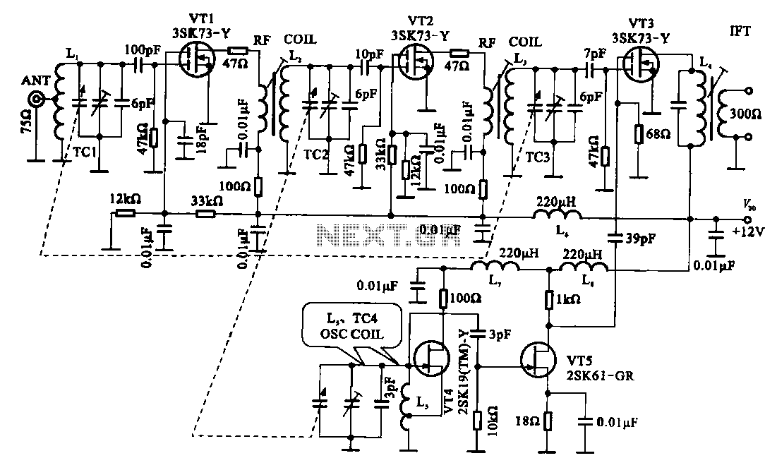
The FM radio circuit is represented by a double-gate MOS field-effect transistor. The high-frequency amplifier is a bipolar MOS field-effect transistor amplifier consisting of transistors VT1 and VT2. VT3 serves as the mixer. The local oscillator is formed by...
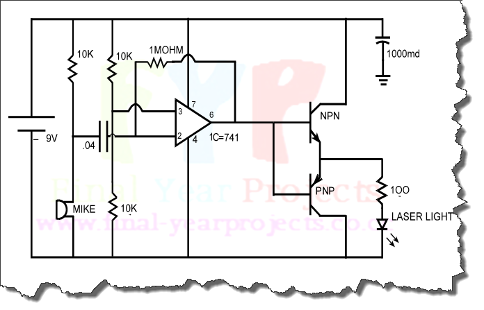
An infrared wired repeater circuit is designed to control appliances from a remote location. Parts List: R1: 1k Resistor (1), R2: 3.3k Resistor (1), R3: 10k Resistor (1). The infrared wired repeater circuit serves as an interface for controlling various...
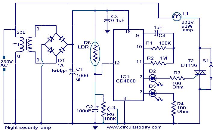
This simple circuit activates a light approximately two hours after midnight, a time when many robberies occur. The circuit is based on a CMOS IC 4060 to achieve the necessary timing. During the daytime, the light-dependent resistor (LDR) has...
The objective of this project is to design a circuit for an electronic infrared communication system, develop innovative ideas for implementing this circuit, and study the circuitry along with various components such as DTMF generators, DTMF decoders, operational amplifiers,...
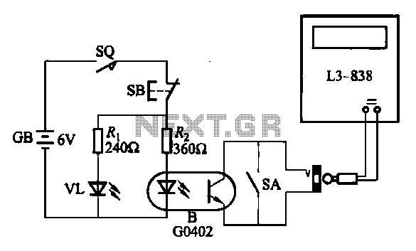
An electronic calculator features an automatic counting interface circuit, as illustrated in the accompanying figures. Figure (a) depicts a stroke switch controlled via optocoupler B. Figure (b) shows the application of a reed switch (KR) for pulse control signals....
This unit captures the ATV signal by sampling the transmission line with minimal insertion loss. It features two N connectors for input and output connections, and a BNC connector is utilized for the video output. The detected output is...