
Fog Lamp Switch Circuit

The fog lamp switch circuit is designed to control the operation of rear fog lights on trailers, ensuring compliance with safety regulations. This circuit typically includes a switch that activates the rear fog lights when the trailer is connected to the towing vehicle.
The circuit consists of a few key components: a fog lamp switch, a relay, and the rear fog light itself. The fog lamp switch is usually mounted on the dashboard of the vehicle, allowing the driver to easily turn the fog lights on or off. When the switch is activated, it sends a signal to the relay, which acts as an electrically operated switch. The relay is necessary to handle the higher current required to power the rear fog light.
In addition to the switch and relay, the circuit may also include a fuse to protect against overcurrent conditions. This fuse is typically rated to handle the maximum current draw of the rear fog light, providing an additional layer of safety.
The wiring for this circuit should be carefully routed to avoid interference with other vehicle systems and to ensure durability under various environmental conditions. Proper connectors and insulation must be used to prevent corrosion and maintain reliable operation.
Overall, the fog lamp switch circuit is a critical component in ensuring that trailers equipped with rear fog lights can operate safely and effectively in low visibility conditions, thereby enhancing road safety for all users.Fog Lamp Switch Circuit Circuit In most countries it is now mandatory or at least recommended to have a rear fog light on a trailer with the additional requirement that, when the trailer is coupled to the car, the rear fog light.. 🔗 External reference
Related Circuits
When this thermometer is utilized in a room environment, it operates intermittently, maintaining this operational state within the temperature measurement circuit due to the stable internal temperature. The astable multiresonance oscillator is composed of transistors VT1 and VT2, forming...
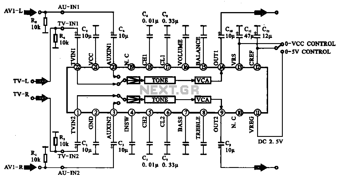
Audio signal control circuit. It illustrates a typical audio signal control circuit where two audio signals enter the integrated circuit through switching and tone controls (treble and bass), subsequently adjusting the output sent to the audio power amplifier. The audio...
The XLR connector facilitates the connection of the microphone's output to the preamplifier circuit. This preamplifier was designed and constructed by Electrical Engineers using discrete components. The signal from the preamplifier is subsequently fed to the Maxim Class-D amplifier....
This is a single-channel (on/off) universal switch that can be used with any infrared remote control operating within wavelengths of 850-950 nm. The single-channel universal switch functions as a simple on/off control mechanism, allowing users to operate electronic devices remotely...
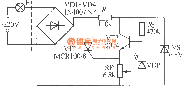
The VDP is a photodiode that exhibits low resistance during the day, approximately 1 kΩ. As a result, transistor VT2 remains off, which keeps thyristor VT1 in the off-state due to the absence of trigger current at the gate,...

The circuit expands a single 15-pin D-sub VGA output to multiple outputs, allowing for the connection of up to six monitors simultaneously. The input VGA connector is positioned on the left side, while the six output VGA connectors are...