
The thermometer circuit composed of LX5600
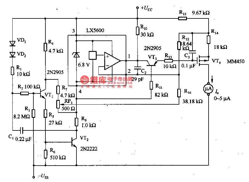
The described thermometer circuit employs an astable multiresonance oscillator configuration, which is key to its intermittent operation. The circuit is designed with two transistors, VT1 and VT2, configured to function as a flip-flop. This configuration allows the thermometer to alternate between high and low states, effectively sampling the ambient temperature at one-second intervals.
The choice of an astable multiresonance oscillator is significant as it provides a stable output frequency, which is essential for consistent temperature readings. The internal temperature of the thermometer remains relatively constant, minimizing fluctuations that could affect measurement accuracy. This characteristic enhances the reliability of the temperature test circuit, ensuring that readings reflect the true ambient conditions without sharp variations.
The interval time ratio of 0 indicates that the oscillator is continuously operating without a defined pause, allowing for real-time monitoring of temperature changes. The output from the oscillator can be fed into a microcontroller or analog readout device, where the sampled data can be processed and displayed.
In summary, this thermometer circuit effectively combines an astable multiresonance oscillator with a stable temperature measurement system, ensuring accurate and reliable temperature readings in a room environment through its intermittent operational capability.When this thermometer is used in the room, it can work in the intermittent way, and this working state can be kept in the temperature test circuit, because internal temperature doesn`t change sharply. The astable multi-resonance oscillator consists of VT1 and VT2, i.e the interval oscillator circuit, which samples per 1s, and the interval time ratio is 0..
🔗 External reference
Related Circuits

The circuit diagram presented below illustrates a portable gas detector. This device primarily utilizes electrochemical sensors and features dual-channel micro-power amplifiers, specifically the ADA4505-2. These amplifiers are configured in both a constant potential (U2-A) and a transconductance configuration (U2-B)....

The high-temperature alarm will emit a beep and the LED will blink when the temperature of the device rises abnormally. This simple overheating alarm is designed to monitor heat levels. The high-temperature alarm circuit is an essential safety device used...

An adjustable pulse generator circuit is presented, which produces a periodic signal with independently adjustable pulse widths. The electrical path allows for modifications to the signal period through the adjustment of RP1. Additionally, RP2 can be altered to change...
The inquiry pertains to identifying the component within the circuit that regulates the minimum RPM achievable. The current operational range of the motor is between 1400 and 3700 RPM, and there is an interest in modifying the circuit to...

The NE555 timer circuit functions as a vibration generator. The input pin 3 produces pulse frequencies ranging from 5 to 20 Hz. The circuit includes a fan that operates within a bamboo enclosure. The barrel section is designed to...

This page features H-Bridge circuits used for controlling direct current motors. Several designs are shown using both CMOS and Bi-Polar power devices. These circuits could be used as the basis for Model Railroad DCC Boosters or PWM motor controllers....
Warning: include(partials/cookie-banner.php): Failed to open stream: Permission denied in /var/www/html/nextgr/view-circuit.php on line 713
Warning: include(): Failed opening 'partials/cookie-banner.php' for inclusion (include_path='.:/usr/share/php') in /var/www/html/nextgr/view-circuit.php on line 713