
Forklift battery circuit
The battery forklift operates on a well-defined electrical and mechanical structure that ensures efficient handling and maneuverability. The series connection of batteries provides a stable 30V DC output, which is essential for powering the motors and hydraulic systems. Motor M1, a two-speed series motor, is designed to deliver torque and speed control through a gear mechanism, facilitating the lifting and lowering of loads. The gear wheel drive system enables the forklift to navigate through tight spaces and perform precise movements.
Motor M2 plays a critical role in the hydraulic system, powering a high-pressure oil pump that enables the lifting mechanism of the forklift. This motor must operate reliably under varying load conditions to maintain the efficiency of the hydraulic system. The integration of the electric lock switch (S1) ensures that the forklift cannot be operated unless it is safe to do so, preventing accidental activation.
The direction switch (S2) allows the operator to select forward or backward movement, enhancing operational flexibility. The foot switch (SO1) serves as a safety feature, ensuring that the forklift can only be activated when the operator is ready and in control. The speed controller pedal (S02) provides a means to modulate the speed of the forklift, allowing for smooth acceleration and deceleration.
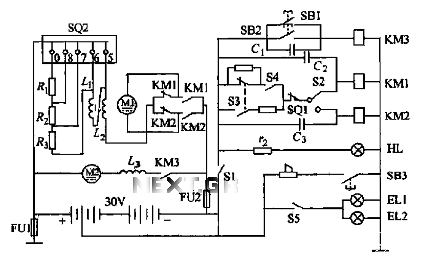
In summary, the design of the battery forklift incorporates essential components such as motors, switches, and control circuitry to create a robust and user-friendly handling tool for various industrial applications. Proper understanding and management of these components are vital for maintaining operational efficiency and safety in the workplace. Battery forklifts are railway stations, docks, warehouses balloon-like plant in two commonly used as a stacking and handling tools. Pictured It forklift battery shape and elect rical control circuitry, circle 2-18b It is composed of batteries in series battery electric forklift electric control path. GB is a concatenation of the 30V DC battery power supply. Motor Ml is driving the motor, series motor is a two-speed, through a gear wheel drive mechanism, drive things forward or backward with the shovel.
Granville string electric motor M2 is the motor for drag high international oil pump, high pressure oil input to the hydraulic system to operate the fork lift. Sl electric lock switch, S2 is a direction switch, soi for the foot switch. s02 speed controller pedal. The forklift and the governor will start the electric lock switch sl closed HL power indicator light, said power had access circuit, make ready supply.
The direction of the switch S2 handle into the desired direction, namely forklift forward or backward position. Release the parking brake handle stern, release the foot brake and the car, so that the foot switch is closed soi reset, and then gently depress the pedal speed controller SQ2 to dynamic contact with the stationary contact 0 contact, so that the entire mace switch S3 closed sets.
Related Circuits
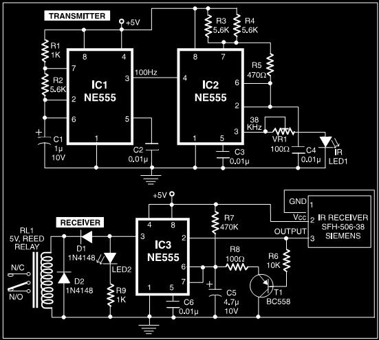
This post discusses a proximity detector circuit primarily utilizing the NE555 integrated circuit (IC). The circuit is designed for burglar alarms based on beam interruption, with the advantage that the transmitter and receiver are contained within the same enclosure,...
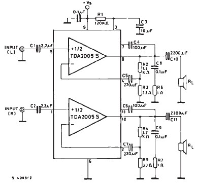
The TDA2005 car audio amplifier circuit is specifically designed for use in devices such as car radios and CD players. This amplifier circuit utilizes the TDA2005 audio integrated circuit (IC), which can deliver a maximum output power of 20...
This 2-meter 144 MHz fox hunt transmitter is utilized in amateur competitions where participants seek to locate a concealed transmitter using primarily homebrewed receivers. The 144 MHz fox hunt transmitter is designed for use in amateur radio competitions, commonly referred...
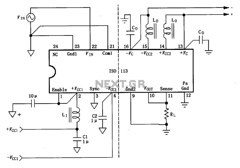
The basic connection circuit for the ISO113 signal and power supply is illustrated. Each power supply terminal must include a bypass filter. If the output current from the isolated power supply exceeds 15mA, it is advisable to utilize an...
.png)
This document describes a simple engineering project circuit for a mobile cell phone detector (sniffer). This compact mobile communication detector can sense the presence of a mobile device, making it suitable for preventing mobile phone usage in private spaces,...
Prior to the test point, there is an AD744 operational amplifier with its output connected to a 10nF capacitor. Following this, a 1kΩ resistor connects to ground. From the junction where the capacitor and resistor meet, a 4.7kΩ resistor...
Warning: include(partials/cookie-banner.php): Failed to open stream: Permission denied in /var/www/html/nextgr/view-circuit.php on line 713
Warning: include(): Failed opening 'partials/cookie-banner.php' for inclusion (include_path='.:/usr/share/php') in /var/www/html/nextgr/view-circuit.php on line 713