
TDA2005 car audio amplifier circuit diagram project

The TDA2005 audio amplifier circuit is an efficient solution for automotive audio applications, offering a robust design that caters to various configurations. The bridge mode operation allows for higher output power, making it suitable for driving larger speakers or subwoofers in a vehicle, while maintaining low distortion levels that enhance audio clarity. The Class B design ensures that the amplifier operates efficiently, minimizing power loss and heat generation.
The Multiwatt 11 package of the TDA2005 facilitates easy integration into existing audio systems, providing a compact footprint that is ideal for space-constrained environments typical in automotive applications. The choice between the TDA2005M and TDA2005S variants allows designers to optimize the circuit for their specific needs, whether prioritizing maximum power output in bridge mode or stereo sound quality.
In terms of protection features, the short circuit protection prevents damage to the amplifier in the event of speaker faults, while the thermal overload protection safeguards against excessive heat buildup, ensuring reliability and longevity of the amplifier in demanding automotive conditions. The ability to operate within a wide input voltage range enhances the versatility of the TDA2005, allowing it to function effectively in various vehicle electrical systems.
Overall, the TDA2005 car audio amplifier circuit is a well-engineered solution that combines power, efficiency, and protection features, making it an excellent choice for enhancing the audio experience in automotive environments.This TDA2005 car audio amplifier circuit is specially designed to work on devices like : car radios, cd-players and similar devices. This car radio audio amplifier circuit is based on the TDA2005 audio IC which can provide a maximum output power of 20 watts into a 4 ohms load, connected in bridge mode configuration.
The TDA2005 audio IC is a c lass B audio amplifier designed in a Multiwatt 11 package and can be ordered in two types TDA2005M used for bridge mode application or TDA2005S used in stereo applications. If the TDA2005 is used in stereo mode it can deliver a 10 + 10 watts output power in a 2 ohms load. The advantage of using the TDA2005 audio amplifier in bridge mode configuration is that the total harmonic distortion ( THD) is 1% and the THD for the stereo configuration mode is 10 %.
This audio amplifier IC supports a wide range of input voltage from 8 volts up to 18 volts and it has many features like : short circuit protection, overrating chip temperature, low external components required, bridge or stereo booster amplifiers with or without boostrapand with programmable gain and bandwidth, no electrical isolation between the package and the heatsink. 🔗 External reference
Related Circuits
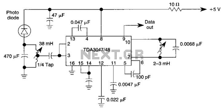
The circuit operates from a 5-V supply and has a current consumption of 2 mA. The output functions as a current source that can drive or suppress a current exceeding 75 mA with a voltage swing of 4.5 V....
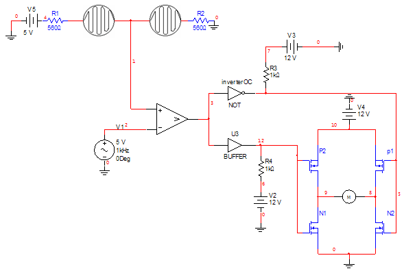
Can someone please help explain how this circuit works? I am confident that I understand how the voltage divider network operates. The circuit in question likely includes a voltage divider configuration, which is a fundamental concept in electronics used to...
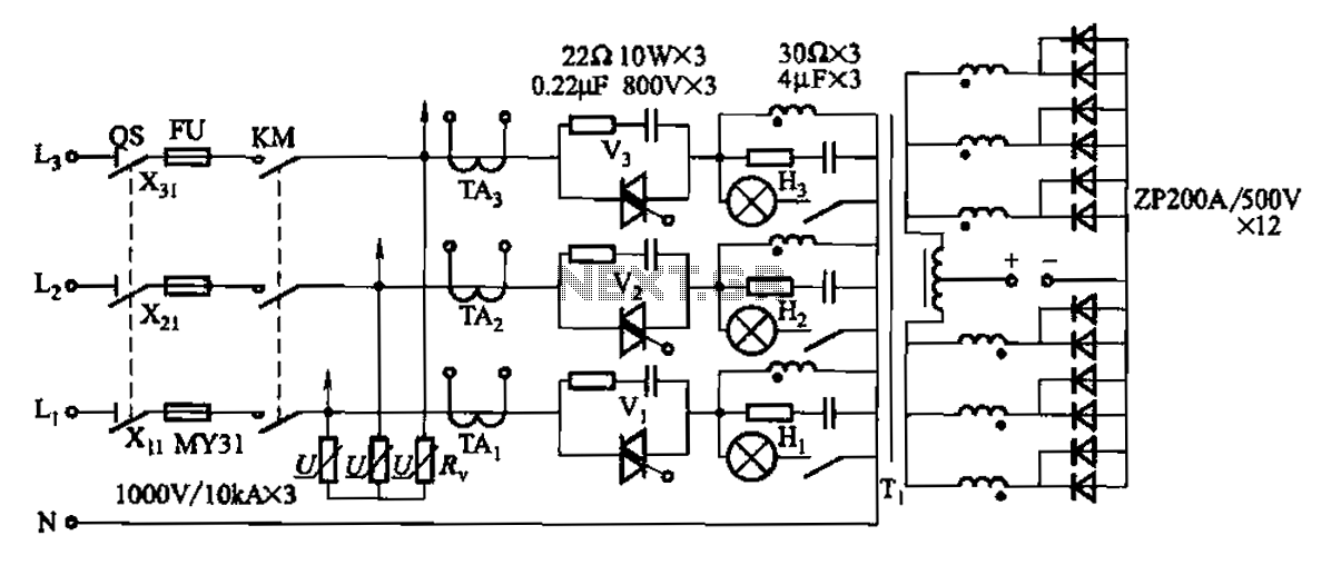
A 1500A-7V phase thyristor power regulator circuit is designed for plating applications. It consists of three major components: the main circuit, the control circuit, and the protection circuit. The control circuit includes a trigger circuit, a synchronous power supply,...

There are important considerations when using additional memory, but it is certainly feasible. The MP3 player project utilizes 32 megabytes of memory. However, using more memory necessitates careful planning. The key factor is that the 8051 processor has a...
This project is based almost directly on the typical application circuit in the National Semiconductor specification sheet. You can also use the TDA2050 (from SGS-Thompson), which has almost identical performance and (remarkably) the same pinouts! As it turns out,...
A basic digital voltmeter circuit utilizing the Harris Semiconductor ICL7107 is presented. It operates within a 2-V range. Calibration involves applying a known voltage of 1.2 V to the input and adjusting resistor R3 to achieve an accurate reading...