
Creating Buffer front end circuit to read AD744
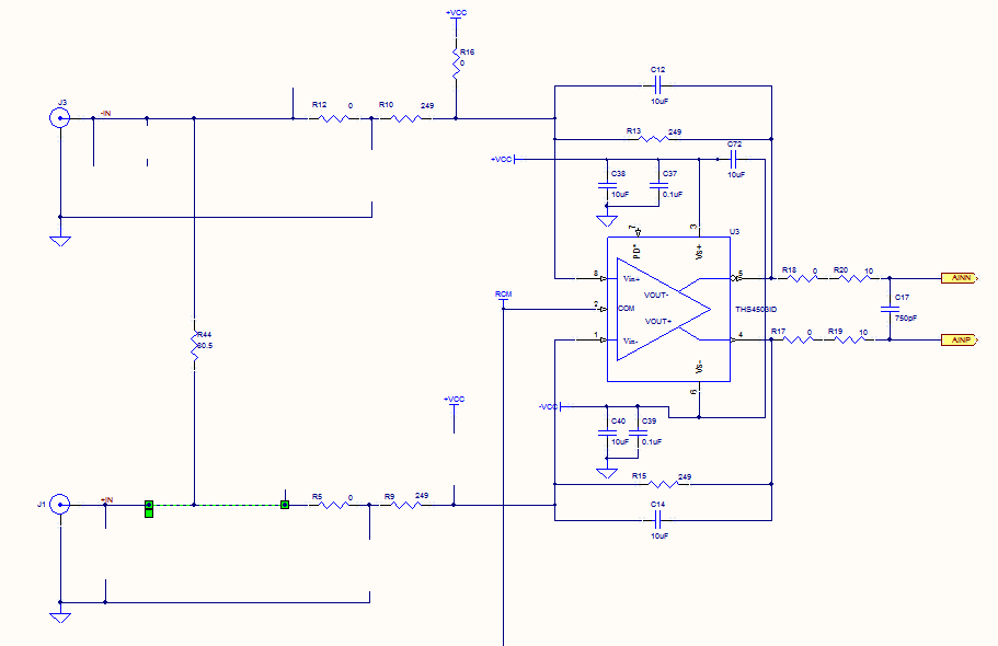
The circuit described involves an AD744 operational amplifier, which is configured to output a voltage signal. The output of the AD744 is coupled through a 10nF capacitor, which serves to block any DC component of the signal while allowing AC signals to pass. This capacitor also plays a role in filtering, potentially smoothing the output signal before it is processed further.
After the capacitor, a 1kΩ resistor is connected to ground. This resistor forms a voltage divider with the capacitor, influencing the time constant of the circuit and affecting the response time of the signal at the junction between the capacitor and the resistor. The combination of the capacitor and the resistor creates a low-pass filter that determines the frequency response of the output signal.
At the junction where the capacitor and the 1kΩ resistor meet, a 4.7kΩ resistor is connected to the test point. This resistor serves to provide a load to the circuit and can also be part of a further signal conditioning stage. The value of the 4.7kΩ resistor suggests that it is designed to allow for a specific voltage drop at the test point, which can be measured for further analysis or testing purposes.
Overall, this circuit configuration is commonly used in signal processing applications where it is crucial to filter out noise and ensure that only the desired frequency components of the signal are passed to the test point for measurement or further processing. The choice of resistor and capacitor values indicates a careful design consideration for achieving the desired electrical characteristics and performance of the circuit.Before the test point there is an AD744 with its output connected to a 10nF capacitor and after there is 1K resistor that goes to GND, from this node of connection of capacitor/resistor there is a 4. 7k resistor that goes to the TEST POINT. 🔗 External reference
Related Circuits
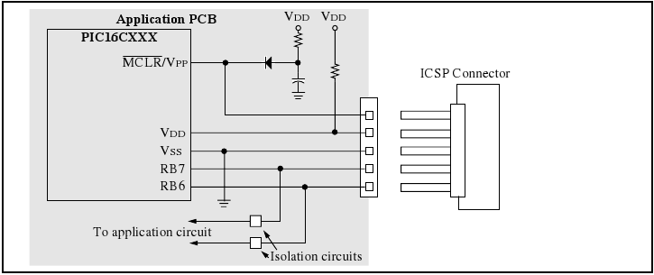
The programmer utilizes a serial signaling scheme to program the chip while it is in-circuit. The signaling is transmitted through the programming clock (PGC or ICSPCLK) and the programming data (PGD or ICSPDAT) pins. Additionally, the MCLR/VPP pin serves...
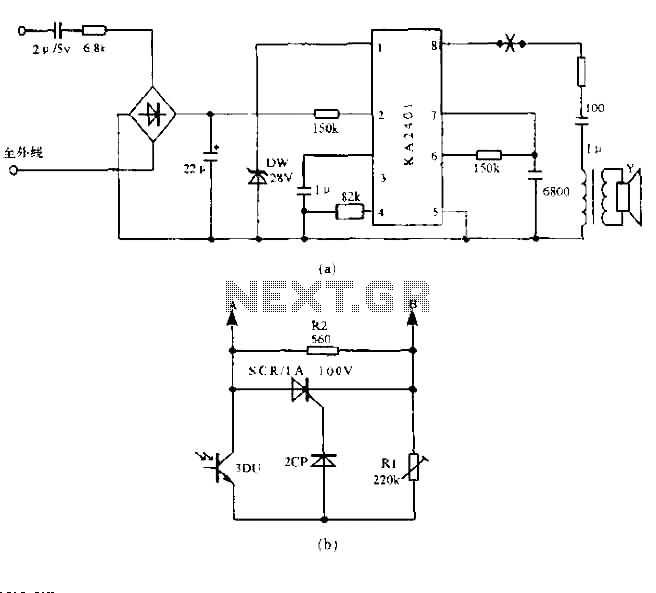
The circuit utilizes a standard telephone ringing circuit, KA2401, along with additional components to control lighting in response to a ringing signal. The light control circuit can be activated externally by AC when the ringing signal is received. The...
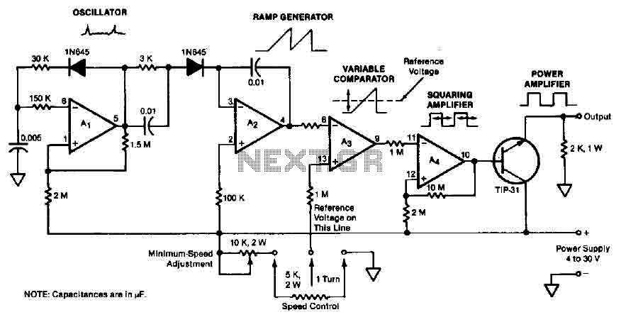
The quad operational amplifier circuit provides a pulse width modulation control ranging from 0 to 100 percent. The controller utilizes an LM3900 and operates with a single supply voltage between 4 to 30 V. A 1 kHz oscillator amplifier,...

This simple temperature relay circuit can be used to signal a fire or setpoint for temperature monitoring function. You need to adjust P1 so that T1's base. The temperature relay circuit operates by monitoring the temperature in a designated area...
With this counter you can count laps for example (in conjunction with the Simple light trap). The circuit uses two TTL ICs 74LSxx the series. The left IC is a decimaalteller. The input pulses 14 are counted and converted...
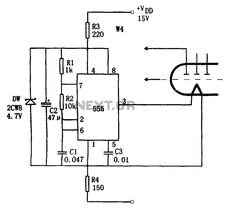
The economic fluorescent display circuit is illustrated in the figure. The primary component of this circuit is the 555 timer configured as a multivibrator. The oscillation frequency is determined by the components R1, R2, and C1, with a frequency...
Warning: include(partials/cookie-banner.php): Failed to open stream: Permission denied in /var/www/html/nextgr/view-circuit.php on line 713
Warning: include(): Failed opening 'partials/cookie-banner.php' for inclusion (include_path='.:/usr/share/php') in /var/www/html/nextgr/view-circuit.php on line 713