
Four channel mixer
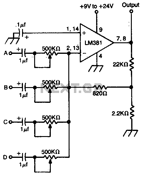
The high-gain operational amplifier (op-amp) circuit is designed to amplify multiple input signals while maintaining signal integrity and minimizing noise. This circuit is particularly useful in applications where signal processing from various sources is required, such as audio mixing or sensor data acquisition.
The op-amp configuration allows for the combination of up to four input signals, each of which can be controlled independently. This can be achieved using a combination of resistors and potentiometers to adjust the gain and balance of each input signal before they are fed into the op-amp. The selection of the op-amp itself is critical; a low-noise, high-gain op-amp is recommended to ensure that the amplification is effective without introducing significant distortion or noise.
To ensure optimal performance, the DC power source should be well-filtered. A battery is preferred due to its low noise characteristics, which help to minimize interference in sensitive applications. If using a power supply, it should include adequate filtering components, such as capacitors and inductors, to reduce ripple and noise.
Additionally, the circuit layout must prioritize shielding to prevent electromagnetic interference (EMI) and radio frequency interference (RFI) from affecting the signal. This can be accomplished by using a metal enclosure or incorporating shielding techniques in the PCB design, such as ground planes and careful routing of signal traces.
Overall, the design of a high-gain op-amp circuit that combines multiple input signals requires careful consideration of component selection, power supply filtering, and shielding techniques to ensure high fidelity and reliable performance in various applications.High gain op amp combines up to four individually controlled input signals The dc power source should be well filtered (battery is ideal), and the circuit should be well shielded to prevent hum pickup. 🔗 External reference
Related Circuits
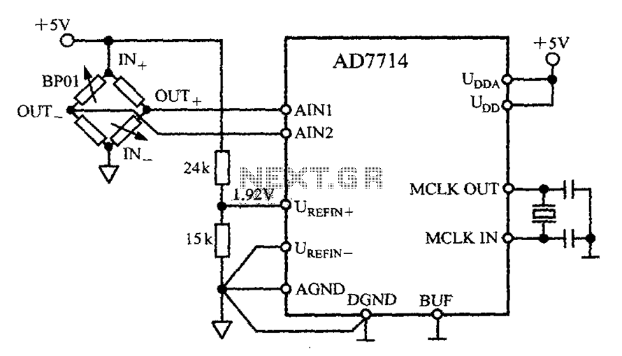
The AD7714 circuit consists of a pressure measurement system featuring the BP01 pressure sensor from Sensym. The BP01 is integrated into a bridge circuit, which produces a differential output voltage. When the sensor is subjected to its rated full-scale...
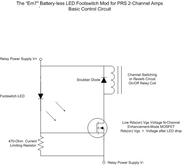
For individuals seeking LED-based footswitching without the inconvenience of battery installation, a battery-less LED-based footswitch modification is being developed for 2-channel amplifiers. This solution is designed to work with the existing TRS jack and footswitch, and it will involve...
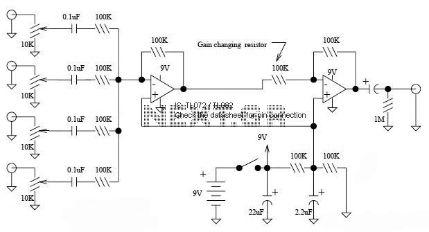
This is a simple mixer featuring four inputs and two operational amplifiers (op-amps). It is designed for mixing microphone signals or effects outputs. The overall gain from input to output is unity when the potentiometer associated with the input...
The interface uses a PIC16F876 microcontroller and not much else. It performs channel mixing, current limiting, and noise rejection. Push the stick forward, both motors move forward, move the stick to the left and the robot moves left. It...
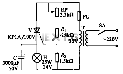
The circuit employs thyristor control. The flash frequency is determined by resistors Ri, RP, Rz, and capacitor C. By adjusting the electrical locator RP, the flash frequency can be varied from 0.5 Hz to several Hz. The described circuit utilizes...
From 230 V AC a DC supply of + 5 V is obtained. The power supply is given to the other blocks. The pulse generator at a particular frequency generates the clock pulses. The clock pulses are counted by...