
6 Channel Disco Running Lights
The circuit described operates by converting 230 V AC into a regulated +5 V DC supply, which powers the various components of the system. The conversion is typically achieved using a transformer to step down the voltage, followed by a rectifier and a voltage regulator to ensure a stable DC output.
The pulse generator, utilizing an IC 555 timer, generates clock pulses at a defined frequency. This IC is configured in astable mode to produce a continuous square wave output, which serves as the timing signal for the subsequent counting operation. The output from the IC 555 is fed into the IC 4017, a decade counter that counts the incoming pulses. The IC 4017 is designed to produce a high output on one of its ten output pins after counting ten clock pulses, allowing for easy sequential control.
The output pins of the IC 4017 are connected to a series of transistors configured as switches. When the IC 4017 activates a transistor, it allows current to flow through the gate of a triac, effectively triggering it. The triac acts as a switch for the load, which in this case consists of decorative bulbs. The triac can handle AC loads and provides sufficient current to light the bulbs.
The sequence in which the bulbs are turned ON and OFF is controlled by the counting mechanism of the IC 4017, which ensures that after every ten pulses, the next bulb in the sequence is activated. This operation can be designed to alternate the bulbs in a forward and reverse manner, creating a visually appealing lighting effect.
In summary, this circuit combines AC to DC conversion, pulse generation, counting, and triac-based switching to achieve a dynamic lighting control system suitable for decorative applications.From 230 V AC a DC supply of + 5 V is obtained. The power supply is given to the other blocks. The pulse generator at a particular frequency generates the clock pulses. The clock pulses are counted by a counter and gives output after every 10 pulses. The counter drives the transistors, which form the triac firing circuit. The transistors fire the triacs and they provide sufficient current to the load. Decorative bulbs are connected as load for each triac. The bulbs are sequentially turned ON and OFF in forward and reverse way. The IC 555 works as the pulse generator and feeds the clock pulses to IC 4017. IC 4017 is the heart of this circuit. It works as a counter and gives the output after every 10 pulses. It drives the transistors, which in turn fire the triacs. The triac provides sufficient current to the load. 🔗 External reference
Related Circuits
The DTMF codec stands for dual-tone multi-frequency codec. The multiple-channel infrared remote control switch circuit that incorporates the DTMF is depicted in the figure. It consists of an infrared remote control signal emitter, an infrared receiving signal amplifier, a...
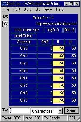
PulsePar turns a PC into a multi-channel pulse generator utilizing the parallel port. The period, duty and phase of each channel are adjustable so as to be used in PWM systems as well as in testing servo and stepper...
The ISL97676 can be utilized as an LED driver capable of managing six channels of LED current for TFT displays. This driver supports the operation of up to 78 LEDs with a voltage range of 4.5V to 26V, or...
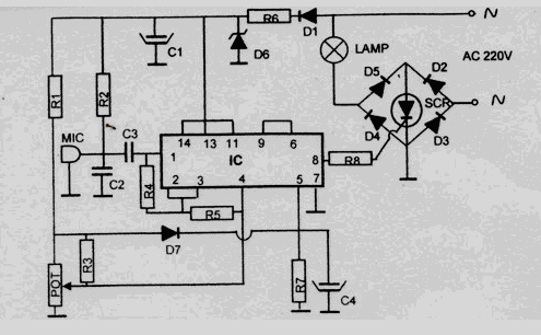
This disco lamp circuit is not a voice-operated switch (VOX) because it cannot differentiate between musical sounds and human voices. Instead, it is sound-activated. An interesting application of this circuit is to control disco lighting automatically using the musical...
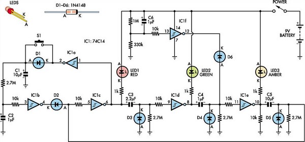
This toy traffic signal utilizes a single, cost-effective hex Schmitt-trigger inverter IC (IC1a-IC1f) to directly control three colored LEDs (red, green, and amber). Upon activation, the circuit illuminates the red signal for 30 seconds, followed by the green signal...
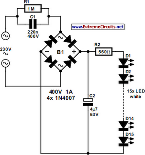
An array of white LEDs can serve as a small lamp for the living room. LED lamps are readily available, resembling standard halogen lamps, and can be installed in a standard 230-V light fixture. A capacitor is employed to...