
Metal Detector Circuit
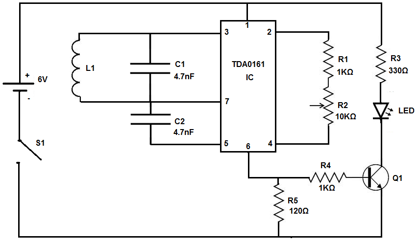
Inductor L1 forms a parallel circuit with capacitor C1, creating an LC parallel circuit. When an oscillating signal in the kilohertz range flows through this circuit, it generates an electric field around the coil. Bringing the coil near a metallic object induces an oscillating signal within the object, which, in turn, creates an electric field that induces current back into the coil. This current alters the oscillating signal within the LC parallel circuit.
The TDA0161 Proximity Detector IC serves as the core of this circuit, supplying the oscillating signal through the LC parallel circuit and responding to any signal changes. Its output is 1 milliamperes (mA) or less when the coil is distant from a metallic object, and 0mA or higher when in proximity to one. Consequently, the IC's output is insufficient to activate the LED when the coil is far from metal, resulting in an unlit LED. Conversely, when the coil is near metal, the IC generates enough current to illuminate the LED.
Resistor R1 and potentiometer R2 are utilized to calibrate the TDA0161 IC to the LC circuit. Calibration is achieved by adjusting the potentiometer to modify the current output based on the metal's proximity to the coil. Increasing the potentiometer resistance results in a lower current output, necessitating closer proximity of metal for the LED to light. Conversely, decreasing the resistance allows the LED to activate with metal at a greater distance.
The 2N3904 transistor (Q1) amplifies the current, ensuring sufficient power to illuminate the LED. Without this transistor, the LED would not receive enough power to operate. The LED functions as an indicator of metal presence; it illuminates when metal is detected and remains off when no metal is nearby.
The circuit operates on a 6-volt power supply, provided by four AA batteries connected in series (1.5V each, totaling 6V). This voltage powers all components of the circuit. An SPST switch is included to enable the user to turn the circuit on or off as desired, functioning as a standard power switch.
The metal detector detects metal through inductor L1. When a metallic object is positioned near L1, it triggers current production from the proximity detector IC, lighting the LED. Testing the circuit involves placing a metallic object near the inductor; the LED should illuminate, and moving the object away should cause it to turn off. Additionally, alternatives to the LED, such as buzzers or alarms, can be incorporated to signal metal detection, provided that power is appropriately allocated for these components.The device we then build will function as a metal detector that can scout out metal objects, such as coins, nails, keys such as car keys you may not be able to find, and even gold if you`re looking for in a beach (though this one may not have industrial strength). This metal detector can detect certain kinds of metal- especially iron-containing me tals, which are called ferrous metals, even if under a half-inch of drywall or sand. How this metal detector works is that it uses an IC that generates an AC signal that goes through a coil. Metal objects are objects which conduct electricity, so a current can be induced in these metal objects.
When the coil in the metal detector comes near a metal object, the electromagnetic field in the coil induces currents in the metal object. The electromagnetic field generated by the metal changes the current in the coil. When the signal changes, the IC turns on an LED< alerting the user to the presence of a metal. Inductor L1- The inductor L1 forms a parallel circuit with the capacitor C1 to form an LC parallel circuit.
When a signal that oscillates at several KHz passes through this circuit, the signal creates an electric field around the coil. When you bring the coil near a metallic object, that electric field induces an oscillating signal in the object.
So when the oscillating signal has been induced in the metallic object, the signal in the object creates an electric field that induces current in the coil. This current changes the oscillating signal running through the LC parallel circuit. TDA0161 Proximity Detector IC- This IC is a proximity detector. This IC suplies the oscillating signal that is sent through the LC parallel circuit. The IC also responds to any changes in the signal. The IC has an output of 1 milliamperes (mA) or less if the coil is far from a metallic object and an output of 0mA or higher if the coil is near a metallic object.
Thus, this IC is at the heart of this circuit. When the object is far from a metallic object, the current which the IC produces is insufficient to drive the LED. Thus, the LED does not turn on. When the coil is near a metallic object, the IC produces sufficient power to drive the LED and it turns on.
Resistor R1 and Potentiometer R2- These resistors are used to calibrate the TDA0161 IC to the LC circuit. You calibrate it by adjusting the potentiometer to change the current output it creates in accordance with the proximity of metal to the coil.
You can adjust so that it can detect metals at the distances which you want it to. By increasing the potentiometer resistance, the IC will create less current output. Therefore, a metal must be placed closer to the coil in order for the LED to light. By decreasing the potentiometer resistance, the IC produces less current output, so the metal doesn`t have to be placed as close to the coil. It`s up to you to set the adjustment. 2N3904 Transistor (Q1)- The 2N3904 transistor provides amplification, so that there is sufficient current to power the LED.
Without this transistor, there would not be enough power to turn on the LED. LED- The LED in the circuit serves as an indicator to when there is a presence of a metal. When a metal is in close proximity to our electronic circuitry, the LED turns on. This shows we have found metal. When the LED is off (not lit), then our metal detector has not detected metal and indicates no metal is in close proximity. 6 volts- The 6 volts is the supply power to the entire circuit. This 6 volts is supplied through 4 AA batteries in series. Being that each battery supplies 1. 5 volts, 4 AA batteries (1. 5V * 4) provides 6V. This 6 volts gives power to every component in the circuit. SPST Switch- The SPST switch allows us to shut off power to the circuit, if we want the metal detector power shut off, just like any electronic device would have.
This just serves asn an on/off switch. This circuit detects metal through the coil, L1. Once metal is placed near the inductor L1, it will trigger current production from the proximity detector IC, which in turn lights the LED. So to test this circuit, just place a metallic object near this inductor. When done, the LED should turn on. When the metallic object is moved away, the LED should shut off. Some may like a metal detector that has an LED that lights up in the presence of a metal, but there are other alternatives you can do.
It doesn`t have to be an LED. It can be a buzzer that sounds off when metal is detected. It can be a piezo buzzer, a siren, an alarm, etc. Any alternative can be possible if power is allocated properly. So keep this in mind if you don`t want an LED to light but a buzzer to sound. 🔗 External reference
Related Circuits
LED sequencer that follows the rhythm of music or speech, powered by a 9V battery, is a portable unit. The basic circuit illuminates up to ten LEDs in sequence, following the beat. The LED sequencer circuit operates by detecting audio...
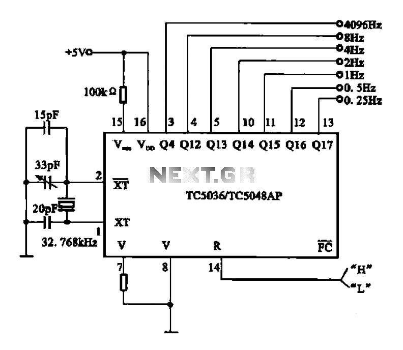
32.768 kHz; In MP3/MP4 devices, mobile phones, laptops, and other digital products, a real-time clock signal generating circuit is utilized, primarily composed of crystal resonators and TC5036/TC5048AP chip oscillators. This setup produces a raw 32.768 kHz crystal oscillator signal,...

The circuit depicted in Figure 3-150 involves a contactor (KM1) that releases when the system is shut down. The contactor KM2 is energized, allowing a 220V AC power supply to flow through diodes VD1 and VD2, which serve as...
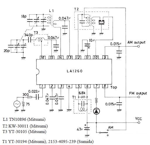
The FM IF MW radio receiver circuit schematic utilizes the LA1260 integrated circuit (IC) for AM and FM radio receiver electronic projects. The LA1260 incorporates numerous functions and features essential for radio receiver applications, including a high signal-to-noise ratio...
An audio test oscillator circuit typically produces a square wave if the oscillation frequency is low enough in relation to the amplifier's bandwidth. This circuit features a crystal-controlled oscillator designed for low-frequency sine wave generation, characterized by low distortion,...
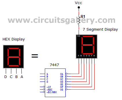
This circuit defines seven levels in a reservoir. The sensed values are connected to an encoder circuit, which consists of a 74148 integrated circuit (IC), functioning as an 8-line to 3-line encoder. The next section features a HEX display,...