
5G169 holiday lights integrated circuit
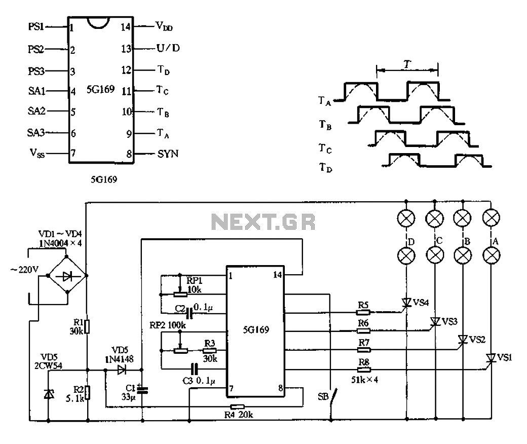
The circuit operates by first converting the alternating current (AC) from the VDI source into direct current (DC) using a full-wave bridge rectifier comprised of four diodes, designated as VD4. This rectification process results in a pulsating DC output that is suitable for powering multiple lighting elements. The output voltage is smoothed and regulated by the combination of components R1, R2, VD5, and VD6. Resistors R1 and R2 help in current limiting and voltage division, while VD5 acts as a simple diode to ensure current flows in the correct direction. VD6 is specifically utilized as a voltage regulator, maintaining the output voltage at a stable 6V DC despite variations in the load or input voltage.
Capacitor C1 plays a crucial role in filtering the pulsating DC output, effectively reducing ripple voltage and providing a more stable DC supply. The ripple frequency, which is double the input AC frequency, is noted to be 100Hz. The circuit includes a mechanism for synchronization, achieved through resistor R4, which injects a signal into the power supply manifold to ensure consistent operation across the circuit.
The operation of the circuit can be controlled using switch SB, which toggles between forward and reverse modes. In the forward mode, the switch is open, allowing current to flow in a designated direction. Conversely, closing the switch reverses the current flow, altering the operation of the connected lights. The configuration detailed in Figure 2-102 outlines the forward loop, indicating the pin outputs from 9 to 12, which are integral to the circuit's functionality. The dashed lines in the figure represent the varying arc light levels, which can be adjusted over a period ranging from 100 milliseconds to 5 seconds, providing flexibility in light intensity and timing for the application.AC by VDI ~ VD4 full-wave bridge rectifier output pulsating DC power for four lights. Rl, R2, VD5 simple composition and VD6 regulator circuit, Cl filtered output by about 6V D C power supply manifold. VD6 here isolators, so to get across R2 6V full-wave pulsating direct current voltage ripple frequency of the alternating current to twice that of 100Hz, 100Hz for this signal by R4 injection manifold 8 feet as a synchronization signal. FIG. SB is forward and reverse control switch, SB open cycle is positive; SB closed reverse circulation. Figure 2-102 is the forward loop convolutions 9 to 12-pin output, the dashed line indicates the arc light levels change, period r adjustable range lOOms ~ 5s.
Related Circuits
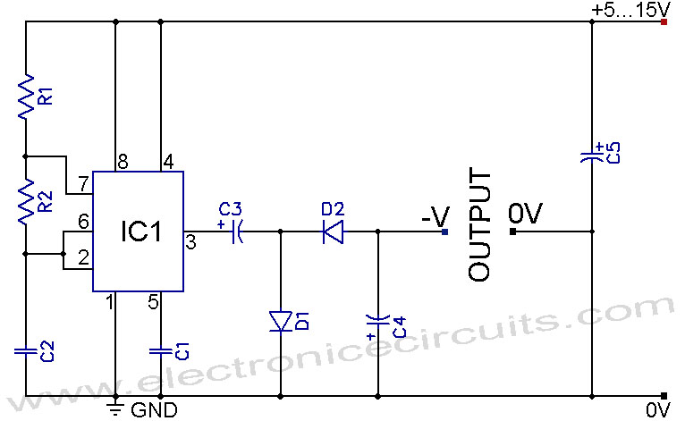
A 555 negative voltage power supply circuit can be created using a charge-pump configuration that incorporates a 555 timer, diodes, and additional components. The 555 timer is a versatile integrated circuit commonly used in various applications, including oscillators, timers, and...
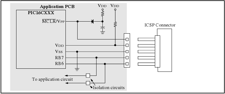
The programmer utilizes a serial signaling scheme to program the chip while it is in-circuit. The signaling is transmitted through the programming clock (PGC or ICSPCLK) and the programming data (PGD or ICSPDAT) pins. Additionally, the MCLR/VPP pin serves...
When the ON/OFF button is pressed once, the equipment goes on and stays on. It goes off when the button is pressed again. The circuit is straightforward. It uses a JK CMOS Flip-Flop with its JK terminals tied high...
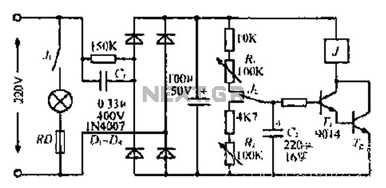
220V mains electricity is sent through a 0.33 µF capacitor (Ci) and a 50 kΩ resistive drop. A bridge rectifier composed of diodes D1 to D4 converts the AC voltage to DC. After passing through a 100 µF capacitor...
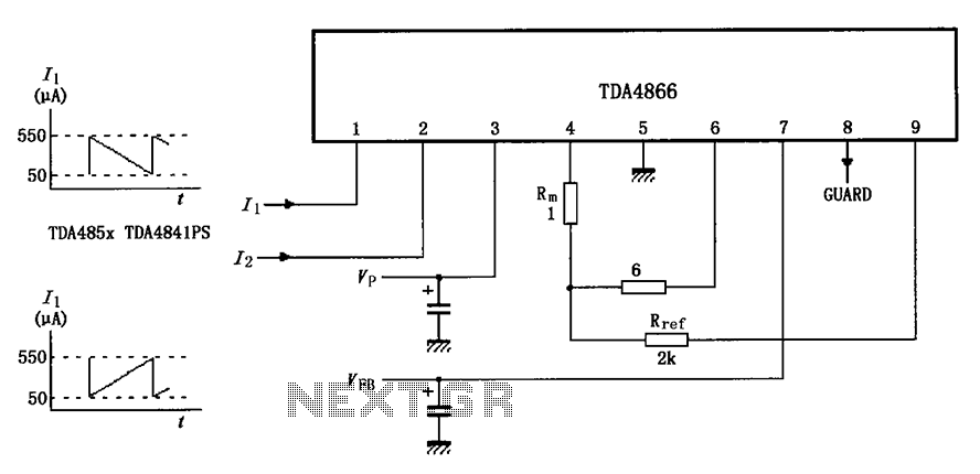
The TDA4866 test circuit operates with a positive supply voltage (VP) and a feedback voltage (VFB) in conjunction with a flyback circuit. The circuit responds to changes in the input signal, transitioning from one state to another. The input...
Standard LED flashers activate the LED in a rapid on-off sequence, which can become bothersome over time. The circuit presented here offers a more gradual illumination effect. This circuit utilizes a simple design to create a soft flashing LED effect,...
Warning: include(partials/cookie-banner.php): Failed to open stream: Permission denied in /var/www/html/nextgr/view-circuit.php on line 713
Warning: include(): Failed opening 'partials/cookie-banner.php' for inclusion (include_path='.:/usr/share/php') in /var/www/html/nextgr/view-circuit.php on line 713