
led dimmer circuit
The LED dimmer circuit employs the LM317T voltage regulator, which is versatile due to its ability to regulate both voltage and current. This characteristic is particularly useful in LED applications where consistent brightness is required. The circuit is designed to accommodate ten super bright white LEDs, allowing for flexibility in the number of LEDs used based on specific lighting needs.
The variable resistor, rated at 200 ohms, serves as a means to adjust the LED brightness by varying the current flowing through the circuit. By changing the resistance, the user can effectively control the luminosity of the LEDs, making this circuit suitable for applications where adjustable lighting is beneficial.
Each LED in the circuit is paired with a current-limiting resistor. This design choice is critical, as it prevents excessive current from damaging the LEDs. The LM317T can supply a maximum current of 1.5A, which is adequate for driving multiple LEDs. However, to ensure longevity and reliability, the inclusion of individual current-limiting resistors for each LED is essential. These resistors are calculated based on the forward voltage and current specifications of the LEDs used, ensuring that each LED operates within its safe limits.
Overall, this LED dimmer circuit is a practical solution for those seeking to create adjustable lighting with super bright LEDs, leveraging the capabilities of the LM317T voltage regulator for optimal performance and safety.Here is a very easy and useful schematic of an LED dimmer circuit. The circuit is using a famous voltage regulator IC LM317T. This IC can also be used as a current regulator, like it is used in the following circuit. In this circuit we have used 10 super bright white LEDs, but the number of LEDs can be increase if desired. The 200 ohms variable r esistor is used to control the current or brightness of LEDs. The total output current of LM317 is 1. 5A, due to which we have used a separate current limiting resistor with each LED which will protect them on the maximum current output from the IC. 🔗 External reference
Related Circuits
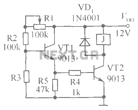
This document presents a brightness control relay circuit. Resistors R1, R2, and R3 create a voltage divider circuit with a light-sensitive resistor. When the light level drops below a specific threshold, the base voltage of VT1 increases, causing VT1...

This article explains how to construct a general-purpose DTMF decoder using an affordable chip from MITEL. The circuit supports DTMF squelch based on a three-digit station ID (covering all 999 combinations). It can also decode four additional commands, which...
A TTL counter, an 8-channel analog multiplexer, and a fourth-order low-pass filter can generate sine waves ranging from 10 kHz to 25 kHz with a total harmonic distortion (THD) better than -80 dB. The circuit employs two cascaded second-order,...
The circuit is directly connected to the AC power line and should be placed inside an enclosure that will prevent direct contact with any of the components. To avoid electrical shock, do not touch any part of the circuit...
The circuit is a bell timer. This project utilizes the AT89S52 microcontroller and an I2C EEPROM for storing alarm timings. Additionally, the 7-segment display has been replaced with an LCD display. The DS1307 is employed for real-time clock functionality....
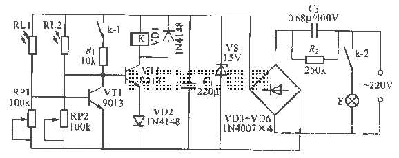
This is a remote-controlled light switch circuit that can be used for remote control toys, flashlight operation, or laser pointers. When the light from a torch illuminates the photosensitive resistor RL2, its resistance decreases, causing transistor VT2 to turn...