
100W full-wave single-junction transistor trigger doer control circuit

The circuit operates by employing a single-junction transistor as the primary control element, enabling the modulation of power to the wire feed motor based on the input control signals. The master potentiometer (RPs) allows for user-defined adjustments to the motor's speed, providing flexibility for various welding applications. The feedback mechanism, facilitated by potentiometer RP4, ensures that the motor responds dynamically to changes in load conditions, maintaining consistent wire feed rates.
Incorporating feedback from the arc voltage is a critical feature of this design. The signals A5 and A6 serve as indicators for the control system, allowing it to determine when to adjust the motor's operation based on the welding conditions. The adjustment of feedback via potentiometer RP6 is essential for tuning the responsiveness of the circuit to variations in arc length, which directly affects welding quality.
As the arc length increases, the circuit compensates by increasing the drive to the motor. This is achieved through a feedback loop that monitors the arc pressure and adjusts the motor's speed accordingly. The design ensures that the welding process remains stable, minimizing the risk of defects caused by inconsistent wire feed rates. Overall, this control circuit exemplifies a robust solution for managing wire feed motors in welding applications, providing both precision and adaptability.100W full-wave single-junction transistor trigger doer control circuit It is suitable for constant or variable speed wire feed control wire feed motor. The input control signal is given voltage (RPs by the Master potentiometer adjustment) and the motor feedback voltage (from potentiometer RP4 taken in) superimposed. When RP4 same position, the motor speed depends on RPs. When using an electric arc voltage feedback control, As, A6 signals the end of the introduction (the amount of feedback is adjusted by potentiometer RP6) quite in RP..
When the arc length increases, the arc pressure is increased when the string l motivation bone incense coupled with feedback voltage increases, I turn to punish Shen j motivation increases, and continue to maintain the original arc welding.
Related Circuits
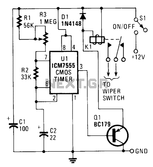
U1 is configured to operate in the standard astable mode, functioning as a relaxation oscillator. When power is applied, C2 initially charges through R1, R2, and R3 to two-thirds of the supply voltage. At this point, U1 detects that...
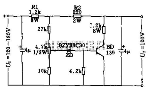
The circuit features no-load and short circuit protection mechanisms. To accommodate short circuit conditions, it is necessary to increase resistors R1 and R2 to allow for power dissipation; for example, R1 can be set to 1.2kΩ with a power...

This circuit provides a straightforward method for converting a loudspeaker into a microphone. When sound waves impact the diaphragm of the speaker, fluctuations occur in the coil, generating a small induced voltage that is typically low in magnitude and...
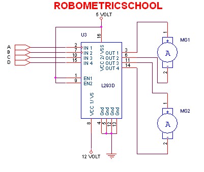
The electronic schematic of a DC motor driver using the L293D, as illustrated in Figure 2, enables the control of two DC motors continuously. It allows for one motor to rotate clockwise while the other rotates counterclockwise. Additionally, all...

A good/bad transistor tester is an instrument designed to determine the operational status of a transistor, indicating whether it is functional or defective. This device provides a simple binary assessment, confirming if the transistor has a gain equal to...
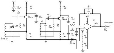
One type of metal detector is a beat frequency oscillator (BFO). The operation of metal detectors relies on changing the characteristics of the oscillator when it is near a metal object detected by the sensor. The detector functions based...