
Wireless Car Alarm circuit diagram
The wireless car alarm system utilizes two primary modules: the transmitter and receiver. The transmitter, which operates on FM radio waves, is designed to be compact and is typically housed within the vehicle. It transmits signals to the receiver, which is strategically placed within the vicinity of the parked vehicle. The CXA1019 FM radio module serves as the heart of the receiver, providing reliable signal reception and processing.
The system is designed to function within a specific voltage range, making it compatible with most automotive power supplies. If a vehicle operates on a higher voltage, such as 24V, a voltage stabilizer is recommended to prevent damage to the circuit components.
When the vehicle is parked, the transmitter remains in a low-power state, continuously sending out a signal. The receiver, tuned to this frequency, remains silent as long as the signal is intact. The absence of noise at the receiver output indicates that the vehicle is secure. The circuit employs a transistor-based relay driver configuration, where the relay is energized when the receiver detects the transmitter's signal.
In the event of unauthorized movement of the vehicle, the disconnection of the transmitter’s signal triggers the FM radio module to generate a hissing sound. This sound is critical as it activates the alarm system. The audio transformer plays a crucial role in coupling the hissing AC signals to the relay circuit, which is then processed through the rectification and filtering stages involving diode D1 and capacitor C8. This ensures that the alarm system is activated promptly upon detection of an intruder.
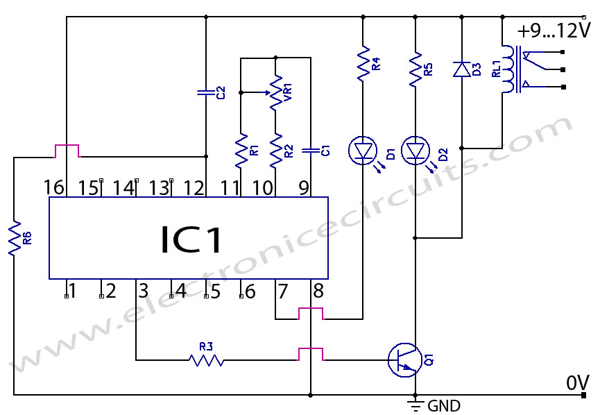
The design emphasizes reliability and tamper-resistance, ensuring that even if an intruder attempts to disable the transmitter, the alarm remains active. The continuous generation of hissing noise in the absence of a signal acts as a fail-safe mechanism, providing an additional layer of security for the vehicle. Overall, the wireless car alarm system presents a robust solution for vehicle protection, leveraging simple yet effective electronic components to ensure a high level of security.This circuit is a wireless car alarm system that is built using two circuit modules, namely modules of transmitter and receiver modules. This circuit works on FM radio waves. Car alarms can be used on vehicles that have a 6-12VDC power supply. You can use the voltage stabilizer if your car power supply is too large (eg 24V). The mini VHF, FM trans mitter is fitted in the vehicle at night when the car is parked in the car porch. The receiver unit is built with CXA1019. CXA1019 a single IC-based FM radio module which is freely available in the market, is kept inside. Receiver is tuned to the transmitter`s frequency. When the transmitter is on and the signals are being received by FM radio receiver, no hissing noise is available at the output of receiver. Thus transistor T2 (BC548) does not conduct. This results in the relay driver transistor T3 getting its forward base bias via 10k resistor R5 and the relay gets energised.
When an intruder tries to drive the car and takes it a few metres away from the car porch, the radio link between the car (transmitter) and alarm (receiver) is broken. As a result FM radio module will generate hissing noise. Hissing AC signals are coupled to relay switching circuit via audio transformer. These AC signals are rectified and filtered by diode D1 and capacitor C8, and the resulting positive DC voltage provides a forward bias to transistor T2.
Thus transistor T2 conducts, and it pulls the base of relay driver transistor T3 to ground level. The relay thus gets de-activated and the alarm connected via N/C contacts of relay is switched on. If the intruder finds out about the wireless alarm (which already turned on) and disconnects the transmitter from battery, still remote alarm remains activated. It will not turn off the alarm because in the absence of signal, the receiver continues to produce hissing noise at its output.
So the burglar alarm is fool-proof and highly reliable. 🔗 External reference
Related Circuits
The internal disconnection circuit for a blanket operates on the principle of induction. It includes a wire approximately 2 cm in length that senses the proximity of a charged mains power source. When the sensing wire is close to...
This digital DIY tachometer for bicycles utilizes two reed switches to gather speed information. The reed switches are positioned near the wheel rim, where permanent magnets, attached to the wheel spokes, pass by and activate the switches. The speed...
CD4060 Timer Circuit 1 minute to 2 hours This is a 1 minute to two-hour timer switch. The 14-stage binary ripple counter Type 4060, IC1, has an... The CD4060 timer circuit is designed to function as a timer switch with...

This model features a pleasant female voice activated by a button press, and includes an alarm function that can wake users up with a rooster sound at a designated time. It also announces the time every hour, which some...

This circuit diagram of a digital clock utilizes six common anode seven-segment displays to indicate the time. It does not require microcontrollers or PICs for operation. The circuit operates using the MM5314 integrated circuit, functioning at either 50 Hz...

Using a power MOSFET, this amplifier can achieve a 2-W handheld radio power level, increasing it to approximately 10 W on the 2-meter band. A transmission-line RF switch is employed for transmit/receive (T/R) switching. The described amplifier utilizes a power...
Warning: include(partials/cookie-banner.php): Failed to open stream: Permission denied in /var/www/html/nextgr/view-circuit.php on line 713
Warning: include(): Failed opening 'partials/cookie-banner.php' for inclusion (include_path='.:/usr/share/php') in /var/www/html/nextgr/view-circuit.php on line 713